Information overhaul kit, supp
Rating:
Scheme ###:
| 000. | [01] | 29400-90630 | OVERHAUL KIT, SUPP | |
| 000. | [01] | 29400-90630 | OVERHAUL KIT, SUPP | |
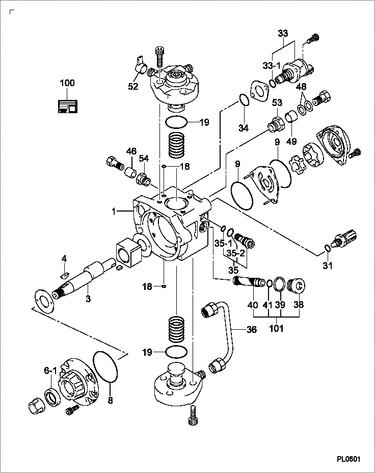
| 001. | [01] | 29410-01280 | HOUSING SUB-ASSY, | |
| 001. | [01] | 29410-01290 | HOUSING SUB-ASSY, | |
| 001. | [01] | 29410-01280 | HOUSING SUB-ASSY, | |
| 001. | [01] | 29410-01290 | HOUSING SUB-ASSY, | |
| 003. | [01] | 29419-10080 | CAMSHAFT, SUPPLY P | |
| 003. | [01] | 29419-10080 | CAMSHAFT, SUPPLY P | |
| 004. | [1C] | 29402-10040 | KEY, WOODRUFF | |
| 004. | [1C] | 29402-10020 | KEY, WOODRUFF | S2289-11200-A |
| 004. | [1C] | 29402-10020 | KEY, WOODRUFF | |
| 004. | [1C] | 29402-10020 | KEY, WOODRUFF | |
| 006-001. | [01] | 29419-70010 | SEAL, OIL | |
| 006-001. | [01] | 29419-70010 | SEAL, OIL | |
| 008. | [01] | 29419-80050 | O-RING, SUPPLY PUM | |
| 008. | [01] | 29419-80050 | O-RING, SUPPLY PUM | |
| 009. | [02] | 29419-80030 | O-RING, SUPPLY PUM | |
| 009. | [02] | 29419-80030 | O-RING, SUPPLY PUM | |
| 012. | [01] | 29418-70040 | KEY, FEED PUMP | |
| 012. | [01] | 29418-70040 | KEY, FEED PUMP | |
| 012. | [01] | 29418-70010 | KEY, FEED PUMP | |
| 012. | [01] | 29418-70010 | KEY, FEED PUMP | |
| 018. | [02] | 29419-80010 | O-RING, SUPPLY PUM | |
| 018. | [02] | 29419-80010 | O-RING, SUPPLY PUM | |
| 019. | [02] | 29419-80040 | O-RING, SUPPLY PUM | |
| 019. | [02] | 29419-80040 | O-RING, SUPPLY PUM | |
| 031. | [01] | 09806-60030 | O-RING, DISTRIBUTI | |
| 031. | [01] | 09806-60030 | O-RING, DISTRIBUTI | |
| 033. | [01] | 29420-00650 | VALVE ASSY, SUCTIO | |
| 033. | [01] | 29420-00650 | VALVE ASSY, SUCTIO | |
| 033. | [01] | 29420-03650 | VALVE ASSY, SUCTIO | |
| 033. | [01] | 29420-03650 | VALVE ASSY, SUCTIO | |
| 033-001. | [01] | 29428-60030 | O-RING, VALVE | |
| 033-001. | [01] | 29428-60030 | O-RING, VALVE | |
| 034. | [01] | 29428-50010 | O-RING, SOLENOID | |
| 034. | [01] | 29428-50010 | O-RING, SOLENOID | |
| 035. | [01] | 29416-00200 | VALVE SUB-ASSY, RE | |
| 035. | [01] | 29416-00130 | VALVE SUB-ASSY, RE | |
| 035. | [01] | 29416-00130 | VALVE SUB-ASSY, RE | |
| 035. | [01] | 29416-00200 | VALVE SUB-ASSY, RE | |
| 035-001. | [01] | 29419-80060 | O-RING, SUPPLY PUM | |
| 035-001. | [01] | 29419-80060 | O-RING, SUPPLY PUM | |
| 035-002. | [01] | 29419-80070 | O-RING, SUPPLY PUM | |
| 035-002. | [01] | 29419-80070 | O-RING, SUPPLY PUM | |
| 036. | [01] | 29401-00110 | PIPE, SUPPLY PUMP | |
| 036. | [01] | 29401-00110 | PIPE, SUPPLY PUMP | |
| 038. | [01] | 29411-50010 | PLUG, FILTER | |
| 038. | [01] | 29411-50010 | PLUG, FILTER | |
| 039. | [01] | 29411-70010 | GASKET, PLUG | |
| 039. | [01] | 29411-70010 | GASKET, PLUG | |
| 040. | [01] | 09737-00010 | FILTER SUB-ASSY | |
| 040. | [01] | 09737-00010 | FILTER SUB-ASSY | |
| 041. | [01] | 09604-90460 | O-RING | |
| 041. | [01] | 09604-90460 | O-RING | |
| 046. | [01] | 94919-80260 | COLLAR, PRESSBOARD | |
| 046. | [01] | 94919-80260 | COLLAR, PRESSBOARD | S2233-21650-A |
| 048. | [02] | 94901-02490 | WASHER | S2287-71100-A |
| 048. | [02] | 94901-02490 | WASHER | |
| 049. | [01] | 94919-80270 | COLLAR, PRESSBOARD | S2284-32240-A |
| 049. | [01] | 94919-80270 | COLLAR, PRESSBOARD | |
| 052. | [01] | 09001-40160 | CAP, VALVE HOLDER | |
| 052. | [01] | 09001-40160 | CAP, VALVE HOLDER | |
| 053. | [01] | 09022-10450 | UNION, INJECTION P | |
| 053. | [01] | 09022-10450 | UNION, INJECTION P | |
| 054. | [01] | 09012-10091 | NIPPLE | |
| 054. | [01] | 09012-10091 | NIPPLE | |
| 100. | [01] | 29400-90640 | OVERHAUL KIT, SUPP | |
| 100. | [01] | 29400-90640 | OVERHAUL KIT, SUPP | |
| 101. | [01] | 29400-90010 | OVERHAUL KIT, SUPP | |
| 101. | [01] | 29400-90010 | OVERHAUL KIT, SUPP |
Include in #3:
Cross reference number
| Part num | Firm num | Firm | Name |
| 29400-90630 | OVERHAUL KIT, SUPP |
Information:
2. Remove the cylinder liners with tool (A) as shown.Install Cylinder Liners
1. Clean the cylinder liners and the liner bores in the cylinder block. 2. Install cylinder liners (1) in the block without the O-ring seals or filler band.3. Check the cylinder liner projection as follows: a) Install the 3/4"-16 NF bolts, 3 in. long and the 2F126 Washers of tooling (A) on the cylinder block next to each liner. Tighten the bolts evenly, in four steps: 10 lb.ft. (14 N m), 25 lb.ft. (35 N m) 50 lb.ft. (70 N m) and then turn to 70 lb.ft. (95 N m).b) Put the adapter plate and one plate of tooling (A) on top of the liner and install the remainder of tooling (A). Be sure the bar is in position at the center of the liner. Tighten the bolts evenly, in four steps to a torque of: 5 lb.ft. (7 N m), 15 lb.ft. (20 N m), 25 lb.ft. (35 N m), then to 50 lb.ft. (70 N m).c) Check to be sure the distance from the bottom edge of the bar to the top of the cylinder block is the same on both sides of the liner. d) Check the cylinder liner projection with tooling (B) at four locations around the liner. SPECIAL INSTRUCTION (GMG00623) is included with the tool.e) Liner projection must be .001 to .006 in. (0.03 to 0.15 mm). Measurements on the same liner must not be different by more than .002 in. (0.05 mm). Average measurements between liners next to each other must not be different by more than .002 in. (0.05 mm).The maximum difference in the average projection for all cylinder liners under one cylinder head must ot be more than .004 in. (0.10 mm). If the liner is turned in the bore it can make a difference in the liner projection.f. If the liner projection is not .001 to .006 in. (0.03 to 0.15 mm), check the thickness of the following parts: spacer plate, spacer plate gasket, and cylinder liner flange (3). The thickness of the spacer plate must be .338 .001 in. (8.59 0.03 mm). The thickness of the spacer plate gasket must be .008 .001 in. (0.20 0.03 mm). The thickness of the cylinder liner flange must be .3500 .0008 in. (8.890 0.020 mm). The cylinder liner projection can be changed by the correction of the counterbore in the block to a minimum depth of .030 in. (0.76 mm) with a cylinder block counterboring tool. See SPECIAL INSTRUCTION, Form FM055228. Shims are available for the adjustment of the liner projection. 5. Put a mark on the liner and block so the liner can be installed in the same position from which it was removed.6. Remove tooling (a) and (B). Remove the liner. Install new O-ring seals on the liners. 7. Put liquid soap on the O-ring seals and on the cylinder bores. Put filler band (2) in SAE 30W oil. Then immediately install
1. Clean the cylinder liners and the liner bores in the cylinder block. 2. Install cylinder liners (1) in the block without the O-ring seals or filler band.3. Check the cylinder liner projection as follows: a) Install the 3/4"-16 NF bolts, 3 in. long and the 2F126 Washers of tooling (A) on the cylinder block next to each liner. Tighten the bolts evenly, in four steps: 10 lb.ft. (14 N m), 25 lb.ft. (35 N m) 50 lb.ft. (70 N m) and then turn to 70 lb.ft. (95 N m).b) Put the adapter plate and one plate of tooling (A) on top of the liner and install the remainder of tooling (A). Be sure the bar is in position at the center of the liner. Tighten the bolts evenly, in four steps to a torque of: 5 lb.ft. (7 N m), 15 lb.ft. (20 N m), 25 lb.ft. (35 N m), then to 50 lb.ft. (70 N m).c) Check to be sure the distance from the bottom edge of the bar to the top of the cylinder block is the same on both sides of the liner. d) Check the cylinder liner projection with tooling (B) at four locations around the liner. SPECIAL INSTRUCTION (GMG00623) is included with the tool.e) Liner projection must be .001 to .006 in. (0.03 to 0.15 mm). Measurements on the same liner must not be different by more than .002 in. (0.05 mm). Average measurements between liners next to each other must not be different by more than .002 in. (0.05 mm).The maximum difference in the average projection for all cylinder liners under one cylinder head must ot be more than .004 in. (0.10 mm). If the liner is turned in the bore it can make a difference in the liner projection.f. If the liner projection is not .001 to .006 in. (0.03 to 0.15 mm), check the thickness of the following parts: spacer plate, spacer plate gasket, and cylinder liner flange (3). The thickness of the spacer plate must be .338 .001 in. (8.59 0.03 mm). The thickness of the spacer plate gasket must be .008 .001 in. (0.20 0.03 mm). The thickness of the cylinder liner flange must be .3500 .0008 in. (8.890 0.020 mm). The cylinder liner projection can be changed by the correction of the counterbore in the block to a minimum depth of .030 in. (0.76 mm) with a cylinder block counterboring tool. See SPECIAL INSTRUCTION, Form FM055228. Shims are available for the adjustment of the liner projection. 5. Put a mark on the liner and block so the liner can be installed in the same position from which it was removed.6. Remove tooling (a) and (B). Remove the liner. Install new O-ring seals on the liners. 7. Put liquid soap on the O-ring seals and on the cylinder bores. Put filler band (2) in SAE 30W oil. Then immediately install