Information pump assy, supply
Rating:
Compare Prices: .
As an associate, we earn commssions on qualifying purchases through the links below

$1,892.00
13 Dec 2023
CN: GEMMOE
1G421-50501 294000-1410 Fuel injection Pump for Kubota Engine V6108-TIE2
Thcbme Part Number: 294000-1410, 2940001410, 1G421-50501, 1G42150501 || Application:for Kubota Engine V6108-TIE2 || High efficiency: for a stable and efficient fuel supply || Ideal replacement: Precision engineered to match specific vehicles || Ensure fit: To make sure this part fits your exact vehicle
Thcbme Part Number: 294000-1410, 2940001410, 1G421-50501, 1G42150501 || Application:for Kubota Engine V6108-TIE2 || High efficiency: for a stable and efficient fuel supply || Ideal replacement: Precision engineered to match specific vehicles || Ensure fit: To make sure this part fits your exact vehicle
Components :
| 001. | PUMP ASSY, SUPPLY | 29400-01410 |
| 002. | OVERHAUL KIT, SUPP | 29400-90031 |
Scheme ###:
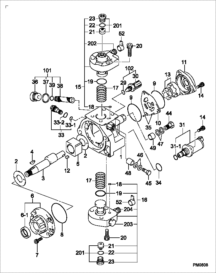
| 000. | [01] | 29400-01410 | PUMP ASSY, SUPPLY | 1G421-50501 |
| 001. | [01] | 29410-01550 | HOUSING SUB-ASSY, | |
| 002. | [02] | 29417-80040 | WASHER, CAMSHAFT | |
| 003. | [01] | 29419-10010 | CAMSHAFT, SUPPLY P | |
| 003. | [01] | 29419-10080 | CAMSHAFT, SUPPLY P | |
| 004. | [01] | 29402-10040 | KEY, WOODRUFF | |
| 004. | [01] | 29402-10020 | KEY, WOODRUFF | |
| 005. | [01] | 29417-00120 | RING SUB-ASSY, CAM | |
| 005. | [01] | 29417-00210 | RING SUB-ASSY, CAM | |
| 006. | [01] | 29412-00310 | COVER SUB-ASSY, BE | |
| 006-001. | [01] | 29419-70010 | SEAL, OIL | |
| 007. | [06] | 09644-90110 | BOLT, SOCKET | |
| 008. | [01] | 29419-80050 | O-RING, SUPPLY PUM | |
| 009. | [02] | 29419-80030 | O-RING, SUPPLY PUM | |
| 010. | [01] | 29418-30160 | PLATE, FEED PUMP, | |
| 011. | [01] | 29418-40080 | COVER, FEED PUMP | |
| 012. | [01] | 29418-70010 | KEY, FEED PUMP | |
| 012. | [01] | 29418-70040 | KEY, FEED PUMP | |
| 013. | [01] | 29418-00080 | ROTOR SET, FEED PU | |
| 014. | [05] | 09644-90050 | BOLT, SOCKET | |
| 015. | [01] | 29409-00640 | ELEMENT KIT, SUPPL | |
| 015. | [01] | 29409-00780 | ELEMENT KIT, SUPPL | |
| 016. | [01] | 29409-00700 | ELEMENT KIT, SUPPL | |
| 016. | [01] | 29409-00770 | ELEMENT KIT, SUPPL | |
| 017. | [02] | 29415-90040 | SPRING, PLUNGER | |
| 018. | [02] | 29419-80010 | O-RING, SUPPLY PUM | |
| 019. | [02] | 29419-80040 | O-RING, SUPPLY PUM | |
| 020. | [06] | 29419-90010 | BOLT, SOCKET | |
| 029. | [01] | 09806-60030 | O-RING, DISTRIBUTI | |
| 030. | [01] | 17973-00100 | SENSOR, FUEL TEMPE | |
| 031. | [01] | 29420-00660 | VALVE ASSY, SUCTIO | |
| 031-001. | [01] | 29428-60010 | O-RING, VALVE | |
| 032. | [01] | 29428-50010 | O-RING, SOLENOID | |
| 033. | [01] | 29416-00200 | VALVE SUB-ASSY, RE | |
| 033. | [01] | 29416-00130 | VALVE SUB-ASSY, RE | |
| 033-001. | [01] | 29419-80060 | O-RING, SUPPLY PUM | |
| 033-002. | [01] | 29419-80070 | O-RING, SUPPLY PUM | |
| 035. | [02] | 29416-90010 | PIN, STOPPER | |
| 036. | [01] | 29411-50010 | PLUG, FILTER | |
| 037. | [01] | 29411-70010 | GASKET, PLUG | |
| 038. | [01] | 09737-00010 | FILTER SUB-ASSY | |
| 039. | [01] | 09604-90460 | O-RING | |
| 044. | [01] | 94918-00310 | SCREW, HOLLOW | 15101-51321 |
| 045. | [01] | 94918-00060 | SCREW, HOLLOW | 15101-51721 |
| 046. | [02] | 94901-02470 | WASHER | |
| 047. | [02] | 94901-02490 | WASHER | |
| 048. | [01] | 94919-80260 | COLLAR, PRESSBOARD | |
| 049. | [01] | 94919-80270 | COLLAR, PRESSBOARD | |
| 052. | [02] | 09001-40180 | CAP, VALVE HOLDER | |
| 101. | [01] | 29400-90010 | OVERHAUL KIT, SUPP | |
| 102. | [01] | 29400-90100 | OVERHAUL KIT, SUPP | |
| 200. | [01] | 29400-90031 | OVERHAUL KIT, SUPP |
Include in #3:
29400-01410
as PUMP ASSY, SUPPLY
Cross reference number
| Part num | Firm num | Firm | Name |
| 29400-01410 | 1G421-5050 | PUMP ASSY, SUPPLY | |
| 1G421-50501 | KUBOTA | PUMP ASSY, SUPPLY |
Information:
Dirty Air Cleaner
If the air cleaner has a restriction indicator, see if the red piston is in view. If there is no restriction indicator, restriction can be checked with a water manometer or a vacuum gauge (which measures in inches of water). Make a connection to the piping between the air cleaner and the inlet of the turbocharger. Check with the engine running at full load rpm. Maximum restriction is 635 mm (25 in) of water. If a gauge is not available, visually check the air cleaner element for dirt. If the element is dirty, clean the element or install a new element.Air Inlet Piping Damage or Restriction
Make a visual inspection of the air inlet system and check for damage to piping, rags in the inlet piping, or damage to the rain cap or the cap pushed too far on the inlet pipe. If no damage is seen, check inlet restriction with a clean air cleaner element.Exhaust System Restriction
Make a visual inspection of the exhaust system. Check for damage to piping or for a bad muffler. If no damage is found, you can check the system by checking the back pressure from the exhaust (pressure difference measurement between exhaust outlet and atmosphere). The back pressure must not be more than 1016 mm (40 in) of water. You can also check by removing the exhaust pipes from the exhaust manifolds. With the exhaust pipes removed, start and load the engine on a chassis dynamometer to see if the problem is corrected.Fuel Injection Timing Not Correct
Check and make necessary adjustments as in