Information pump assy, supply
Rating:
Compare Prices: .
As an associate, we earn commssions on qualifying purchases through the links below

Fuel Injection Pump Cover 294184-0030 294184-0140 294184-0220 for Denso Pump 294000-0030 294000-1180 294000-1290 294000-1840 294000-2270 294000-2600
FGNTWP Part Number: 294184-0030, 294184-0140, 294184-0220, 2941840030, 2941840140, 2941840220 || Application:for Denso Pump 294000-0030 294000-1180 294000-1290 294000-1840 294000-2270 294000-2600
FGNTWP Part Number: 294184-0030, 294184-0140, 294184-0220, 2941840030, 2941840140, 2941840220 || Application:for Denso Pump 294000-0030 294000-1180 294000-1290 294000-1840 294000-2270 294000-2600

294000-1292 294000-1290 Fuel Injection Pump Compatible with Kubota Engine V3800DI
KoovDem Item Type: Fuel Injection Pump || Part Number: 294000-1292 294000-1290 294000-1291 1G381-50502 1G381-50501 1G381-50500 2940001292 2940001290 2940001291 1G38150502 1G38150501 1G38150500 || The V3800DI engine is a powerful and efficient choice for heavy-duty applications. Its robust construction and advanced technology deliver impressive performance and reliability. Whether in construction, agriculture, or industrial vehicles, this engine ensures smooth operation and superior power output. Its innovative design allows for optimal fuel efficiency and low emissions, making it environmentally friendly. A dependable and durable option for demanding tasks requiring high performance. || Suitable for use with the Kubota Engine V3800DI. || Please provide a valid physical address for delivery; we are not able to deliver to P.O. boxes.
KoovDem Item Type: Fuel Injection Pump || Part Number: 294000-1292 294000-1290 294000-1291 1G381-50502 1G381-50501 1G381-50500 2940001292 2940001290 2940001291 1G38150502 1G38150501 1G38150500 || The V3800DI engine is a powerful and efficient choice for heavy-duty applications. Its robust construction and advanced technology deliver impressive performance and reliability. Whether in construction, agriculture, or industrial vehicles, this engine ensures smooth operation and superior power output. Its innovative design allows for optimal fuel efficiency and low emissions, making it environmentally friendly. A dependable and durable option for demanding tasks requiring high performance. || Suitable for use with the Kubota Engine V3800DI. || Please provide a valid physical address for delivery; we are not able to deliver to P.O. boxes.

You can express buy:

USD 19.99
10-11-2022
10-11-2022
USD 19.99
10-11-2022
10-11-2022

USD 48
10-11-2022
10-11-2022
Images:
USD 32

[31-May-2018]
USD 29.2

[10-Nov-2022]
Components :
| 001. | PUMP ASSY, SUPPLY | 29400-01290 |
| 001. | PUMP ASSY, SUPPLY | 29400-01290 |
| 002. | OVERHAUL KIT, SUPP | 29400-90031 |
Scheme ###:
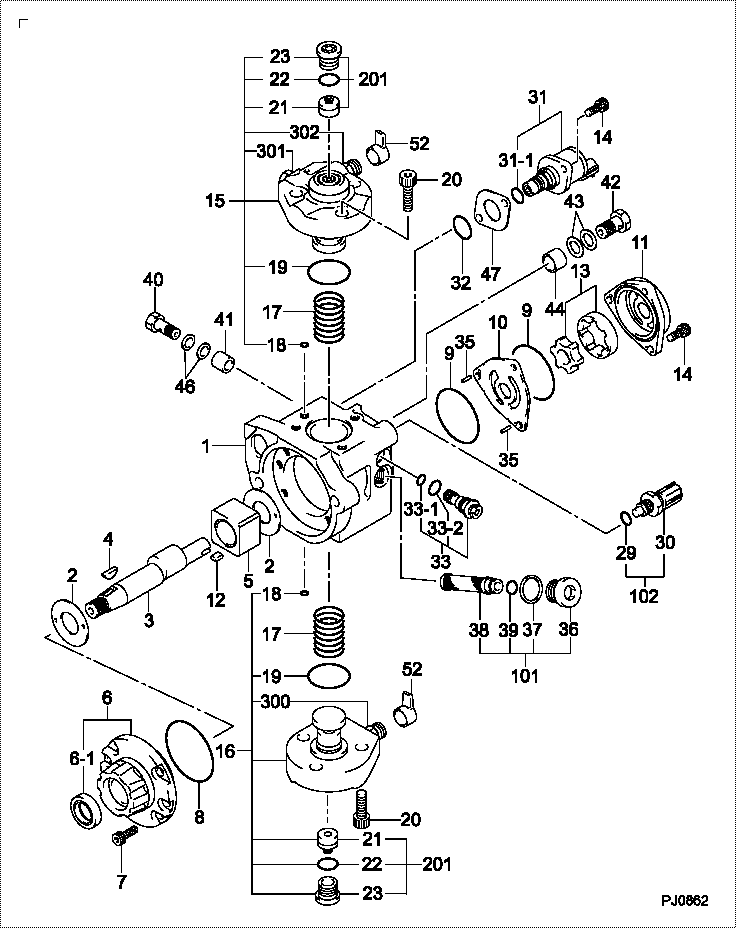
| 000. | [01] | 29400-01291 | PUMP ASSY, SUPPLY | 1G381-50501 |
| 000. | [01] | 29400-01292 | PUMP ASSY, SUPPLY | 1G381-50502 |
| 001. | [01] | 29410-00850 | HOUSING SUB-ASSY, | |
| 002. | [02] | 29417-80040 | WASHER, CAMSHAFT | |
| 003. | [01] | 29419-10010 | CAMSHAFT, SUPPLY P | |
| 003. | [01] | 29419-10080 | CAMSHAFT, SUPPLY P | |
| 004. | [01] | 29402-10020 | KEY, WOODRUFF | |
| 004. | [01] | 29402-10040 | KEY, WOODRUFF | |
| 005. | [01] | 29417-00210 | RING SUB-ASSY, CAM | |
| 005. | [01] | 29417-00120 | RING SUB-ASSY, CAM | |
| 006. | [01] | 29412-00310 | COVER SUB-ASSY, BE | |
| 006-001. | [01] | 29419-70010 | SEAL, OIL | |
| 007. | [06] | 09644-90110 | BOLT, SOCKET | |
| 008. | [01] | 29419-80050 | O-RING, SUPPLY PUM | |
| 009. | [02] | 29419-80030 | O-RING, SUPPLY PUM | |
| 010. | [01] | 29418-30170 | PLATE, FEED PUMP, | |
| 011. | [01] | 29418-40140 | COVER, FEED PUMP | |
| 012. | [01] | 29418-70010 | KEY, FEED PUMP | |
| 012. | [01] | 29418-70040 | KEY, FEED PUMP | |
| 013. | [01] | 29418-00080 | ROTOR SET, FEED PU | |
| 014. | [05] | 09644-90050 | BOLT, SOCKET | |
| 015. | [01] | 29409-00160 | ELEMENT KIT, SUPPL | |
| 015. | [01] | 29409-00770 | ELEMENT KIT, SUPPL | |
| 016. | [01] | 29409-00640 | ELEMENT KIT, SUPPL | |
| 016. | [01] | 29409-00300 | ELEMENT KIT, SUPPL | |
| 017. | [02] | 29415-90040 | SPRING, PLUNGER | |
| 018. | [02] | 29419-80010 | O-RING, SUPPLY PUM | |
| 019. | [02] | 29419-80040 | O-RING, SUPPLY PUM | |
| 020. | [06] | 29419-90010 | BOLT, SOCKET | |
| 021. | [02] | 29414-00082 | VALVE SUB-ASSY, SU | |
| 021. | [02] | 29414-00150 | VALVE SUB-ASSY, SU | |
| 022. | [02] | 29419-80020 | O-RING, SUPPLY PUM | |
| 023. | [02] | 29413-50010 | PLUG, CYLINDER | |
| 029. | [01] | 09806-60030 | O-RING, DISTRIBUTI | |
| 030. | [01] | 17973-00100 | SENSOR, FUEL TEMPE | |
| 031. | [01] | 29420-00370 | VALVE ASSY, SUCTIO | |
| 031-001. | [01] | 29428-60030 | O-RING, VALVE | |
| 032. | [01] | 29428-50040 | O-RING, SOLENOID | |
| 033. | [01] | 29416-00011 | VALVE SUB-ASSY, RE | |
| 033. | [01] | 29416-00200 | VALVE SUB-ASSY, RE | |
| 033-001. | [01] | 29419-80060 | O-RING, SUPPLY PUM | |
| 033-002. | [01] | 29419-80070 | O-RING, SUPPLY PUM | |
| 035. | [02] | 29416-90010 | PIN, STOPPER | |
| 036. | [01] | 29411-50010 | PLUG, FILTER | |
| 037. | [01] | 29411-70010 | GASKET, PLUG | |
| 038. | [01] | 09737-00010 | FILTER SUB-ASSY | |
| 039. | [01] | 09604-90460 | O-RING | |
| 040. | [01] | 94918-00060 | SCREW, HOLLOW | 15101-51721 |
| 041. | [01] | 94919-80260 | COLLAR, PRESSBOARD | |
| 042. | [01] | 94918-00310 | SCREW, HOLLOW | 15101-51321 |
| 043. | [02] | 94901-02490 | WASHER | |
| 044. | [01] | 94919-80270 | COLLAR, PRESSBOARD | |
| 046. | [02] | 94901-02470 | WASHER | |
| 047. | [01] | 29425-90020 | GASKET, SOLENOID | |
| 052. | [02] | 09001-40180 | CAP, VALVE HOLDER | |
| 101. | [01] | 29400-90010 | OVERHAUL KIT, SUPP | |
| 102. | [01] | 29400-90100 | OVERHAUL KIT, SUPP | |
| 200. | [01] | 29400-90031 | OVERHAUL KIT, SUPP | |
| 201. | [02] | 29400-90370 | OVERHAUL KIT, SUPP | |
| 201. | [02] | 29400-90940 | OVERHAUL KIT, SUPP | |
| 300. | [01] | 29409-05010 | ELEMENT KIT, SUPPL | |
| 300. | [01] | 29409-05060 | ELEMENT KIT, SUPPL | |
| 301. | [01] | 29409-05020 | ELEMENT KIT, SUPPL | |
| 301. | [01] | 29409-05070 | ELEMENT KIT, SUPPL | |
| 302. | [01] | 29413-10220 | HOLDER, DELIVERY V |
Cross reference number
| Part num | Firm num | Firm | Name |
| 29400-01290 | PUMP ASSY, SUPPLY | ||
| 1G381-50502 | KUBOTA | PUMP ASSY, SUPPLY | |
| 1G381-50501 | KUBOTA | PUMP ASSY, SUPPLY |
Information:
1. Use tool (A) to remove the engine oil filter. 2. Remove bolts (1) and the washers that hold the tube to the oil pump elbow. Remove bolts (2) and the washers that hold oil pump elbow (3) to the cylinder block. 3. Remove four bolts (4) and the washers that hold the engine oil pump to the front housing. Remove the engine oil pump and the oil pump elbow as a unit. The following steps are for the installation of the engine oil pump.4. Check the condition of the O-ring seal used at the tube-to-oil pump elbow connection and the O-ring seal used on the engine oil pump. If the seals are worn or damaged, use new parts for replacement.5. Install the O-ring seal in the oil pump elbow. Install the O-ring seal on the engine oil pump. Lubricate the bore in the front housing with clean engine oil. Put the engine oil pump in position in the front housing.6. Install four bolts (4) and the washers that hold the engine oil pump to the front housing.7. Install two bolts (2) and the washers that hold the oil pump elbow to the cylinder block.8. Install two bolts (1) and the washers that hold the tube to the oil pump elbow.9. Install the engine oil filter. Follow the instructions with the oil filter assembly for correct installation.Disassemble & Assemble Engine Oil Pump
Start By:a. remove engine oil pump 1. Remove oil pump elbow (1) from the engine oil pump. Remove the two O-ring seals from the oil pump elbow. Remove four bolts (2) and the washers. Remove cover (3) from the pump housing. 2. Remove O-ring seal (4) and idler gear (5) from the cover.3. Using tool (A), remove gear (6) from the drive shaft.
Before removing drive shaft (7) from the pump housing, be sure no burrs exist on the drive shaft. If the drive shaft has burrs, it may scratch the bores in the pump housing.
4. Remove drive shaft (7) from the pump housing. The following steps are for the assembly of the engine oil pump.5. Be sure all parts of the engine oil pump are thoroughly clean prior to assembly. Check the condition of the O-ring seals used in the engine oil pump and on the oil pump elbow. If the seals are worn or damaged, use new parts for replacement. Lubricate all internal parts of the engine oil pump with clean engine oil. 6. Install drive shaft (7) in the pump housing. Heat gear (6) to a maximum temperature of 316°C (601°F). Install gear (6) on the end of drive shaft (7). Position the gear so the distance between the outside face of the gear and the step face on the pump body is 29.40 0.50 mm (1.157 .020 in).7. Install idler gear (5) in the pump housing.8. Install O-ring seal (4) in cover (3). Install cover (3) and four bolts (2) and the washers that hold it. 9. Install the two O-ring seals