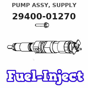
Information pump assy, supply
Rating:
Components :
| 001. | PUMP ASSY, SUPPLY | 29400-01270 |
| 002. | OVERHAUL KIT, SUPP | 29400-90031 |
| 003. | OVERHAUL KIT, SUPP | 29400-90080 |
Scheme ###:
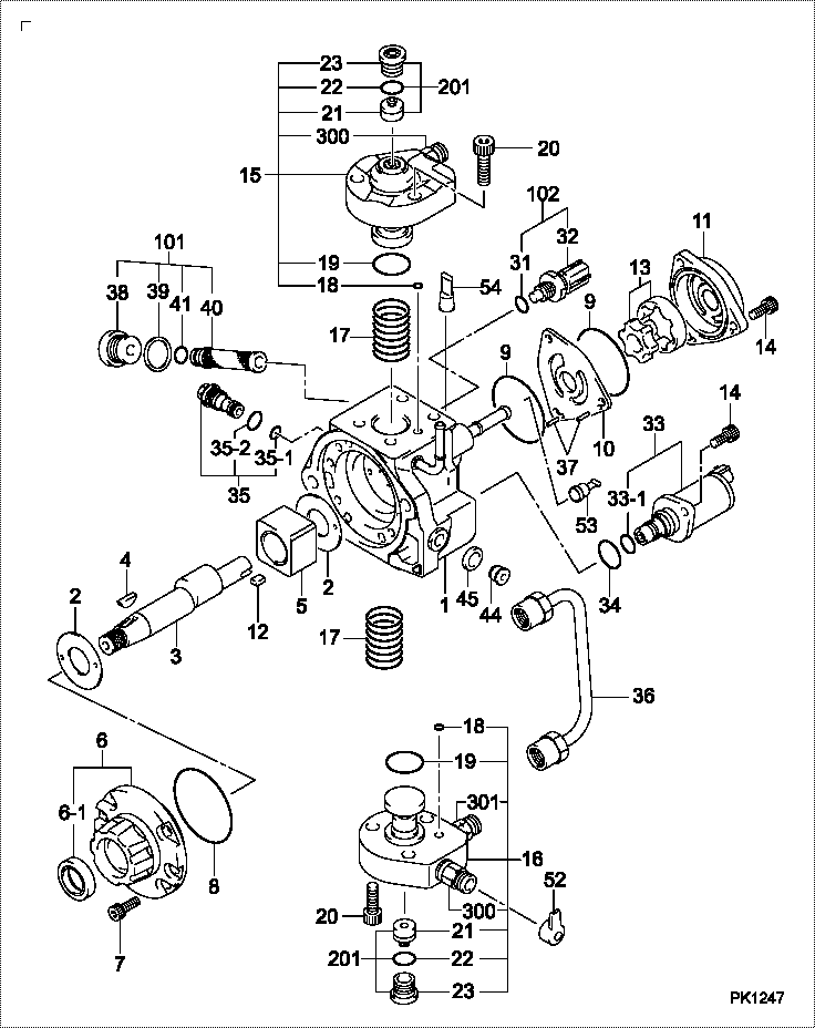
| 000. | [01] | 29400-01270 | PUMP ASSY, SUPPLY | 1460A050 |
| 001. | [01] | 29410-01270 | HOUSING SUB-ASSY, | SM |
| 001. | [01] | 29410-01270 | HOUSING SUB-ASSY, | |
| 002. | [02] | 29417-80060 | WASHER, CAMSHAFT | SM |
| 002. | [02] | 29417-80040 | WASHER, CAMSHAFT | |
| 003. | [01] | 29419-10090 | CAMSHAFT, SUPPLY P | |
| 003. | [01] | 29419-10040 | CAMSHAFT, SUPPLY P | |
| 003. | [01] | 29419-10110 | CAMSHAFT, SUPPLY P | SM |
| 003. | [01] | 29419-10060 | CAMSHAFT, SUPPLY P | SM |
| 004. | [01] | 29402-10020 | KEY, WOODRUFF | |
| 004. | [01] | 29402-10040 | KEY, WOODRUFF | |
| 005. | [01] | 29417-00220 | RING SUB-ASSY, CAM | |
| 005. | [01] | 29417-00260 | RING SUB-ASSY, CAM | SM |
| 006. | [01] | 29412-00330 | COVER SUB-ASSY, BE | SM |
| 006. | [01] | 29412-00310 | COVER SUB-ASSY, BE | |
| 006-001. | [01] | 29419-70010 | SEAL, OIL | |
| 007. | [06] | 09644-90110 | BOLT, SOCKET | ME736324 |
| 007. | [06] | 09644-90380 | BOLT, SOCKET | SM |
| 008. | [01] | 29419-80120 | O-RING, SUPPLY PUM | SM |
| 008. | [01] | 29419-80050 | O-RING, SUPPLY PUM | |
| 009. | [02] | 29419-80100 | O-RING, SUPPLY PUM | SM |
| 009. | [02] | 29419-80030 | O-RING, SUPPLY PUM | |
| 010. | [01] | 29418-30170 | PLATE, FEED PUMP, | |
| 010. | [01] | 29418-30200 | PLATE, FEED PUMP, | SM |
| 011. | [01] | 29418-40160 | COVER, FEED PUMP | SM |
| 011. | [01] | 29418-40160 | COVER, FEED PUMP | |
| 012. | [01] | 29418-70030 | KEY, FEED PUMP | |
| 012. | [01] | 29418-70050 | KEY, FEED PUMP | |
| 013. | [01] | 29418-00110 | ROTOR SET, FEED PU | |
| 013. | [01] | 29418-00100 | ROTOR SET, FEED PU | SM |
| 014. | [05] | 09644-90370 | BOLT, SOCKET | SM |
| 014. | [05] | 09644-90050 | BOLT, SOCKET | |
| 015. | [01] | 29409-00530 | ELEMENT KIT, SUPPL | |
| 015. | [01] | 29409-01040 | ELEMENT KIT, SUPPL | SM |
| 015. | [01] | 29409-00530 | ELEMENT KIT, SUPPL | SM |
| 016. | [01] | 29409-00560 | ELEMENT KIT, SUPPL | SM |
| 016. | [01] | 29409-01050 | ELEMENT KIT, SUPPL | SM |
| 016. | [01] | 29409-00560 | ELEMENT KIT, SUPPL | |
| 017. | [02] | 29415-90040 | SPRING, PLUNGER | |
| 018. | [02] | 29419-80010 | O-RING, SUPPLY PUM | |
| 018. | [02] | 29419-80080 | O-RING, SUPPLY PUM | SM |
| 019. | [02] | 29419-80110 | O-RING, SUPPLY PUM | SM |
| 019. | [02] | 29419-80040 | O-RING, SUPPLY PUM | |
| 020. | [06] | 29419-90010 | BOLT, SOCKET | |
| 020. | [06] | 29419-90030 | BOLT, SOCKET | SM |
| 031. | [01] | 29419-80150 | O-RING, SUPPLY PUM | SM |
| 031. | [01] | 09806-60030 | O-RING, DISTRIBUTI | |
| 032. | [01] | 17973-00100 | SENSOR, FUEL TEMPE | |
| 033. | [01] | 29420-00660 | VALVE ASSY, SUCTIO | |
| 033-001. | [01] | 29428-60010 | O-RING, VALVE | |
| 034. | [01] | 29428-50020 | O-RING, SOLENOID | SM |
| 034. | [01] | 29428-50010 | O-RING, SOLENOID | |
| 035. | [01] | 29416-00160 | VALVE SUB-ASSY, RE | |
| 035. | [01] | 29416-00120 | VALVE SUB-ASSY, RE | |
| 035. | [01] | 29416-00210 | VALVE SUB-ASSY, RE | SM |
| 035. | [01] | 29416-00160 | VALVE SUB-ASSY, RE | SM |
| 035. | [01] | 29416-00120 | VALVE SUB-ASSY, RE | SM |
| 035-001. | [01] | 29419-80130 | O-RING, SUPPLY PUM | SM |
| 035-001. | [01] | 29419-80060 | O-RING, SUPPLY PUM | |
| 035-002. | [01] | 29419-80140 | O-RING, SUPPLY PUM | SM |
| 035-002. | [01] | 29419-80070 | O-RING, SUPPLY PUM | |
| 036. | [01] | 29401-00200 | PIPE, SUPPLY PUMP | |
| 036. | [01] | 29401-00121 | PIPE, SUPPLY PUMP | SM |
| 037. | [02] | 29416-90010 | PIN, STOPPER | |
| 038. | [01] | 29411-50031 | PLUG, FILTER | SM |
| 038. | [01] | 29411-50010 | PLUG, FILTER | |
| 039. | [01] | 29411-70010 | GASKET, PLUG | |
| 039. | [01] | 29411-70020 | GASKET, PLUG | SM |
| 040. | [01] | 09737-00050 | FILTER SUB-ASSY | SM |
| 040. | [01] | 09737-00010 | FILTER SUB-ASSY | |
| 041. | [01] | 29419-80160 | O-RING, SUPPLY PUM | SM |
| 041. | [01] | 09604-90460 | O-RING | |
| 044. | [01] | 09031-70060 | PLUG, SCREW | ME702176 |
| 045. | [01] | 94901-02470 | WASHER | |
| 052. | [01] | 09001-45170 | CAP, VALVE HOLDER | SM |
| 052. | [01] | 09001-40180 | CAP, VALVE HOLDER | |
| 053. | [01] | 09808-10100 | COVER, RUBBER | SM |
| 053. | [01] | 09808-10020 | COVER, RUBBER | |
| 054. | [01] | 09646-80060 | CAP RUBBER | |
| 054. | [01] | 09808-10110 | COVER, RUBBER | SM |
| 101. | [01] | 29400-90010 | OVERHAUL KIT, SUPP | SM |
| 101. | [01] | 29400-90010 | OVERHAUL KIT, SUPP | |
| 102. | [01] | 29400-90100 | OVERHAUL KIT, SUPP | SM |
| 102. | [01] | 29400-90100 | OVERHAUL KIT, SUPP | |
| 200. | [01] | 29400-90031 | OVERHAUL KIT, SUPP | |
| 200. | [01] | 29400-90080 | OVERHAUL KIT, SUPP | SM |
| 201. | [02] | 29400-90940 | OVERHAUL KIT, SUPP | |
| 300. | [02] | 29409-05010 | ELEMENT KIT, SUPPL | |
| 301. | [01] | 29413-10220 | HOLDER, DELIVERY V |
Include in #3:
29400-01270
as PUMP ASSY, SUPPLY
Cross reference number
| Part num | Firm num | Firm | Name |
| 29400-01270 | 1460A050 | PUMP ASSY, SUPPLY | |
| 1460A050 | MITSUBISHI | PUMP ASSY, SUPPLY |
Information:
Basic Block
Cylinder Block Honing
The following preliminary check is essential to determine if honing is necessary, and if so, the size to hone.Measure all cylinder bores during disassembly using the 1P3537 Bore Gauging Group. This Group includes a 1P3535 Dial Bore Gauge Group and a 1P3536 Size Setting Fixture Group. The bore gauging group provides more accurate measurement than other methods, such as inside micrometers. When setting the gauge, always be sure the gauge pin has sufficient travel to measure the points of maximum wear in the bore. In a cylinder bore, maximum wear is usually across the diameter perpendicular to the crankshaft centerline, either at the top or bottom of ring travel. Normal wear usually will not exceed 0.51 mm (.020 in); however, if bore wear is greater than 0.51 mm (.020 in), hone the block 1.02 mm (.040 in) oversize. The fact that the block can be honed both 0.51 mm (.020 in) and 1.02 mm (.040 in) oversize will allow a block to be reconditioned twice under normal wear conditions. The standard bore size is 114.300 to 114.338 mm (4.5000 to 4.5015 in).
1P3537 Bore Gauging GroupWhen reconditioning an engine, the bore size is the determining factor as to the necessity of honing the bores. If bores are worn 0.15 mm (.006 in) more than the standard size, the block should be honed. However, additional service may be obtained without honing if wear does not exceed the maximum wear limit of 0.216 mm (.0085 in).Before honing, inspect the bottom of each cylinder bore adjacent to the main bearing saddle or web. Some of the saddles may overlap the edge of cylinder bores enough to interfere with honing. Where overlap exists, machine a relief in the saddle to provide clearance for the honing tool. The radius of the relief must be concentric with the cylinder bore and 0.76 0.13 mm (.030 .005 in) larger than the bore radius. The relief extends 15.7 mm (.62 in) beyond the bottom of the bore, as shown. This provides adequate clearance for honing.
Relief In Saddles And Chamfer After HoningWhen honing, check bore size at several locations in the length of the bore and around the circumference. Specifically measure at points perpendicular to the crankshaft centerline at locations 6.4 mm (.25 in) from each end and at center of bore. These three specific locations are primary gauge points during and after honing.
Primary Gauging PointsWhen honing cylinder blocks, maintain the specific dimensional surface finish and cross hatch tolerances to obtain satisfactory oil control. The tolerances specified are virtually the same as those used for original bore finish at the factory, and can be obtained with an automatic honing machine such as the Sunnen CK-10. This machine has been evaluated and found to give satisfactory results.The Sunnen CK-10 machine is available from Sunnen Products Company, 7910 Manchester Avenue, St. Louis, Missouri, 63143.Due to the cost of suitable honing equipment, it may be more expedient to have the honing done by a shop equipped