Information pump assy, supply
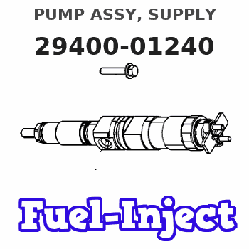
PUMP ASSY, SUPPLY
EA
- *1 SIAM DENSO PRODUCTION SM294000-124#
Rating:
Compare Prices: .
As an associate, we earn commssions on qualifying purchases through the links below

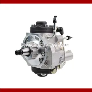
Fuel injection Pump 294000-1240 2940001240 for Mitsubishi Engine 4D56 Truck L200
100% Apollo part number:294000-1240 2940001240 || application: for Mitsubishi Engine 4D56 Truck L200
100% Apollo part number:294000-1240 2940001240 || application: for Mitsubishi Engine 4D56 Truck L200

WZCNLXLX Common Rail Pump 294000-1240 1460A057 for Mitsubishi Pajero L200 4D56 HP Di-D 4WD Engine
WZCNLXLX Item Name:Fuel Injection Pump || Item Number:1460A057 294000-1240 2940001240 || Application:for Mitsubishi Pajero L200 4D56 HP, Di-D 4WD Engine || Note: If you are unsure if the product is suitable.In order not to delay your use of the parts, please provide your engine nameplate or serial number and part number, and we will help you confirm if it is suitable. To avoid unnecessary returns, please check the product image and part number to ensure it is the product you want. || Tip: Please contact us - we are a professional sales team and we have many products to offer to you. Many buyers are very satisfied with our service. You can get first-class products and high-quality services from us, believe me, you will have a pleasant shopping experience here.
WZCNLXLX Item Name:Fuel Injection Pump || Item Number:1460A057 294000-1240 2940001240 || Application:for Mitsubishi Pajero L200 4D56 HP, Di-D 4WD Engine || Note: If you are unsure if the product is suitable.In order not to delay your use of the parts, please provide your engine nameplate or serial number and part number, and we will help you confirm if it is suitable. To avoid unnecessary returns, please check the product image and part number to ensure it is the product you want. || Tip: Please contact us - we are a professional sales team and we have many products to offer to you. Many buyers are very satisfied with our service. You can get first-class products and high-quality services from us, believe me, you will have a pleasant shopping experience here.

You can express buy:
USD 392.84
29-05-2025
29-05-2025
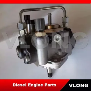
New fuel pump 294000-1372 1460A053 294000-1242 294000-0641 294000-1240 1460A057
USD 480
19-05-2025
19-05-2025
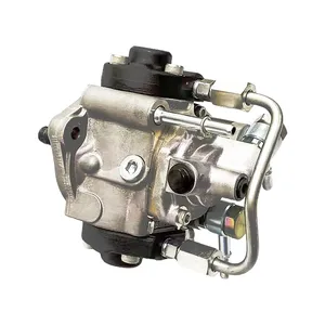
Diesel Fuel Injection Pump 294000-1240 1460A001 1460A047 1460A057 1460A097 FOR MITSUBISHI 4D56 TRITON / CHALLENGER
USD 398.84
19-05-2025
19-05-2025
New fuel pump 294000-1372 1460A053 294000-1242 294000-0641 294000-1240 1460A057
Images:
USD 383.46

[29-May-2025]
USD 393.14

[13-May-2025]
USD 406

[13-May-2025]
USD 395.3

[13-May-2025]
Components :
| 001. | PUMP ASSY, SUPPLY | 29400-01240 |
| 002. | OVERHAUL KIT, SUPP | 29400-90080 |
Scheme ###:
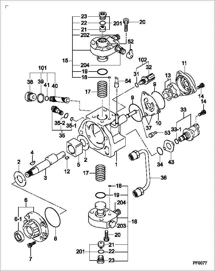
| 000. | [01] | 29400-01240 | PUMP ASSY, SUPPLY | 1460A057 |
| 001. | [01] | 29410-00561 | HOUSING SUB-ASSY, | SM |
| 002. | [02] | 29417-80060 | WASHER, CAMSHAFT | SM |
| 003. | [01] | 29419-10060 | CAMSHAFT, SUPPLY P | SM |
| 003. | [01] | 29419-10110 | CAMSHAFT, SUPPLY P | SM |
| 004. | [01] | 29402-10040 | KEY, WOODRUFF | |
| 004. | [01] | 29402-10020 | KEY, WOODRUFF | |
| 005. | [01] | 29417-00260 | RING SUB-ASSY, CAM | SM |
| 006. | [01] | 29412-00330 | COVER SUB-ASSY, BE | SM |
| 006-001. | [01] | 29419-70010 | SEAL, OIL | |
| 007. | [06] | 09644-90380 | BOLT, SOCKET | SM |
| 008. | [01] | 29419-80120 | O-RING, SUPPLY PUM | SM |
| 009. | [02] | 29419-80100 | O-RING, SUPPLY PUM | SM |
| 010. | [01] | 29418-30141 | PLATE, FEED PUMP, | SM |
| 011. | [01] | 29418-40130 | COVER, FEED PUMP | SM |
| 012. | [01] | 29418-70030 | KEY, FEED PUMP | |
| 012. | [01] | 29418-70050 | KEY, FEED PUMP | |
| 013. | [01] | 29418-00100 | ROTOR SET, FEED PU | SM |
| 014. | [05] | 09644-90370 | BOLT, SOCKET | SM |
| 015. | [01] | 29409-00750 | ELEMENT KIT, SUPPL | SM |
| 015. | [01] | 29409-00540 | ELEMENT KIT, SUPPL | SM |
| 016. | [01] | 29409-00550 | ELEMENT KIT, SUPPL | SM |
| 016. | [01] | 29409-00770 | ELEMENT KIT, SUPPL | SM |
| 017. | [02] | 29415-90040 | SPRING, PLUNGER | |
| 018. | [02] | 29419-80080 | O-RING, SUPPLY PUM | SM |
| 019. | [02] | 29419-80110 | O-RING, SUPPLY PUM | SM |
| 020. | [06] | 29419-90030 | BOLT, SOCKET | SM |
| 031. | [01] | 29419-80150 | O-RING, SUPPLY PUM | SM |
| 032. | [01] | 17973-00100 | SENSOR, FUEL TEMPE | |
| 033. | [01] | 29420-00360 | VALVE ASSY, SUCTIO | SM |
| 033-001. | [01] | 29428-60030 | O-RING, VALVE | SM |
| 034. | [01] | 29428-50030 | O-RING, SOLENOID | SM |
| 035. | [01] | 29416-00210 | VALVE SUB-ASSY, RE | SM |
| 035. | [01] | 29416-00160 | VALVE SUB-ASSY, RE | SM |
| 035. | [01] | 29416-00120 | VALVE SUB-ASSY, RE | SM |
| 035-001. | [01] | 29419-80130 | O-RING, SUPPLY PUM | SM |
| 035-002. | [01] | 29419-80140 | O-RING, SUPPLY PUM | SM |
| 036. | [01] | 29401-00071 | PIPE, SUPPLY PUMP | SM |
| 037. | [02] | 29416-90010 | PIN, STOPPER | |
| 038. | [01] | 29411-50031 | PLUG, FILTER | SM |
| 039. | [01] | 29411-70020 | GASKET, PLUG | SM |
| 040. | [01] | 09737-00050 | FILTER SUB-ASSY | SM |
| 041. | [01] | 29419-80160 | O-RING, SUPPLY PUM | SM |
| 043. | [01] | 29425-90020 | GASKET, SOLENOID | |
| 052. | [01] | 09001-45170 | CAP, VALVE HOLDER | SM |
| 053. | [01] | 09808-10100 | COVER, RUBBER | SM |
| 054. | [01] | 09808-10110 | COVER, RUBBER | SM |
| 101. | [01] | 29400-90010 | OVERHAUL KIT, SUPP | SM |
| 102. | [01] | 29400-90100 | OVERHAUL KIT, SUPP | SM |
| 200. | [01] | 29400-90080 | OVERHAUL KIT, SUPP | SM |
Include in #3:
29400-01240
as PUMP ASSY, SUPPLY
Cross reference number
| Part num | Firm num | Firm | Name |
| 29400-01240 | 1460A057 | PUMP ASSY, SUPPLY | |
| 1460A057 | MITSUBISHI | PUMP ASSY SUPPLY |
Information:
2. Turn the crankshaft until two pistons are at bottom center.3. Remove connecting rod caps (1) from the two connecting rods. Put pieces of rubber hose or tape on the threads of the connecting rod bolts as protection for the crankshaft. 4. Push the pistons and connecting rods away from the crankshaft until the piston rings are above the cylinder block.5. Remove the two pistons (2) and the connecting rods. Keep each connecting rod cap with its respective connecting rod and piston. Put identification on each connecting rod as to its location for use at installation.
Do not turn the crankshaft while any of the connecting rods are in the engine without the caps installed.
6. Do Steps 2 through 5 for the remainder of the pistons.Install Pistons
Two different pistons are used in 3208 Truck Engines. One piston has a crater volume of 50.4 1.3 cm3 (3.08 .07 in.3), and the other piston has a crater volume of 58.8 1.2 cm3 (3.59 .07 in.3). Check the part number stamped on the top of the piston and refer to the parts book to be sure the correct replacement piston is used. The correct piston must be installed in the engine. If the wrong piston is installed, much damage to the engine will be the result.
1. Put clean engine oil on the piston rings, connecting rod bearings, cylinder walls and crankshaft bearing journals.2. Turn the crankshaft until the bearing journal for the pistons to be installed is at bottom center.3. Make sure the piston ring gaps are at least 120° apart on the piston. 4. Use tool (A) and install the piston in position in the same cylinder bore from which it was removed. The hole (crater) in the top of the piston must be toward (nearest) the center of the engine. For more detail about the installation of connecting rod bearings, see REMOVE AND INSTALL CONNECTING ROD BEARINGS.5. Check the bearing clearances with tool (B).6. Put 2P2506 Thread Lubricant on the threads of the bolts and contact surfaces of the nuts for the connecting rod caps.
When the connecting rod caps are installed, make sure that the number on the side of the cap is next to and respective with the number on the side of the connecting rod.
7. Put the cap (1) in position on the connecting rod and install the nuts. Tighten the nuts to a torque of 40 4 N m (30 3 lb.ft.). Put a mark on each nut and the end of each bolt. Tighten the nuts 60 5° more. 8. Check the side clearance between two connecting rods on the same crankshaft journal. Clearance must be 0.08 to 0.84 mm (.003 to .033 in.) for new rods.9. Do Steps 1 through 8 for the remainder of the pistons.end by:a) install cylinder headsb) install oil panDisassemble Pistons
start by:a) remove pistons1. Remove the rings from the piston with tool (A). 2. Remove the bearings from the connecting rod and connecting rod