Information pump assy, supply
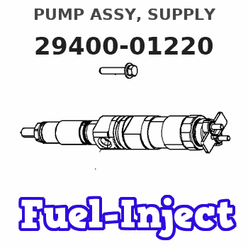
PUMP ASSY, SUPPLY
IA
- * DMHU DENSO PRODUCTION HU294000-122#
- #..CHANGE OVER DATE UNSCHEDULED.
Rating:
Compare Prices: .
As an associate, we earn commssions on qualifying purchases through the links below

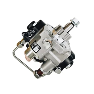
Fuel Injection Pump for Nissan Navara Pathfinder D40 D22 R51 YD25 YD25DDTI 2.5L Euro V 2005-2015 Engine 16700-5X00A 16700-5X00B 294000-1223 294000-1220
KoovDem Part Number: 294000-1223, 294000-1220 || OEM Part Number: 16700-5X00A, 16700-5X00B, 16700-5X00C, 16700-5X00D, 16700-5X00E, 167005X00A, 167005X00B, 167005X00C, 167005X00D, 167005X00E, 16700-5X01B, 167005X01B || Compatible with Nissan Navara, Pathfinder, and D40, D22, R51 models with YD25 and YD25DDTI 2.5L Euro V engines from 2005 to 2015. || Effective and Reliable: Utilizing cutting-edge technology, this system delivers effective and reliable fuel supply, guaranteeing smooth vehicle performance. || Rugged and Dependable: With a track record of being rigorously tested and proven, this product offers durability and reliability, ensuring it operates consistently even in the harshest of environments.
KoovDem Part Number: 294000-1223, 294000-1220 || OEM Part Number: 16700-5X00A, 16700-5X00B, 16700-5X00C, 16700-5X00D, 16700-5X00E, 167005X00A, 167005X00B, 167005X00C, 167005X00D, 167005X00E, 16700-5X01B, 167005X01B || Compatible with Nissan Navara, Pathfinder, and D40, D22, R51 models with YD25 and YD25DDTI 2.5L Euro V engines from 2005 to 2015. || Effective and Reliable: Utilizing cutting-edge technology, this system delivers effective and reliable fuel supply, guaranteeing smooth vehicle performance. || Rugged and Dependable: With a track record of being rigorously tested and proven, this product offers durability and reliability, ensuring it operates consistently even in the harshest of environments.

294000-1223 294000-1220 16700-5X00A 16700-5X00B Fuel Injection Pump for Nissan Navara Pathfinder D40 D22 R51 YD25 YD25DDTI 2.5L Euro V 2005-2015 Engine
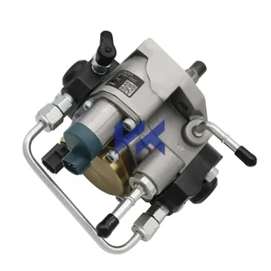
HIRINTOL 🔸Replace Part Number: 294000-1223, 294000-1220 || 🔸OEM Part Number: 16700-5X00A, 16700-5X00B, 16700-5X00C, 16700-5X00D, 16700-5X00E, 167005X00A, 167005X00B, 167005X00C, 167005X00D, 167005X00E, 16700-5X01B, 167005X01B || 🔸Compatible Model: for Nissan Navara Pathfinder D40 D22 R51 YD25 YD25DDTI 2.5L Euro V 2005-2015 Engine || 🔸Efficient And Stable: Using advanced technology, it can provide efficient and stable fuel supply to ensure the normal operation of the vehicle. || 🔸Durable And Reliable: Tested and proven many times, it has a long life and reliable quality to keep working under extreme conditions.
HIRINTOL 🔸Replace Part Number: 294000-1223, 294000-1220 || 🔸OEM Part Number: 16700-5X00A, 16700-5X00B, 16700-5X00C, 16700-5X00D, 16700-5X00E, 167005X00A, 167005X00B, 167005X00C, 167005X00D, 167005X00E, 16700-5X01B, 167005X01B || 🔸Compatible Model: for Nissan Navara Pathfinder D40 D22 R51 YD25 YD25DDTI 2.5L Euro V 2005-2015 Engine || 🔸Efficient And Stable: Using advanced technology, it can provide efficient and stable fuel supply to ensure the normal operation of the vehicle. || 🔸Durable And Reliable: Tested and proven many times, it has a long life and reliable quality to keep working under extreme conditions.

High pressure fuel injection pump Fits for NISSAN YD25 DCi D40 NAVARA NV350 2.5L 294000-1223 294000-1220 16700-5X00E 16700-5X00D
KoovDem Part Number: 294000-1223 294000-1220 16700-5X00E 16700-5X00D || Product Name: 294000-1223 294000-1220 16700-5X00E 16700-5X00D High pressure fuel injection pump || Suitable for NISSAN YD25 DCi D40 NAVARA NV350 2.5L engines. Ideal for those looking for reliable and efficient performance. Specifically designed to meet the needs of NISSAN vehicles with these engine specifications. Perfect for enhancing the overall performance and longevity of your vehicle. A compatible choice for those seeking the best fit and quality for their NISSAN YD25 DCi D40 NAVARA NV350 2.5L engine. || A single high-pressure fuel injection pump. || . Our team will assist you in verifying the compatibility of the part with your engine. It is essential to ensure that you are purchasing the correct product to avoid any issues during installation or operation. Feel free to reach out to us for any assistance or clarification regarding the product or its compatibility with your engine. Your satisfaction is our priority. Thank you for your cooperation.
KoovDem Part Number: 294000-1223 294000-1220 16700-5X00E 16700-5X00D || Product Name: 294000-1223 294000-1220 16700-5X00E 16700-5X00D High pressure fuel injection pump || Suitable for NISSAN YD25 DCi D40 NAVARA NV350 2.5L engines. Ideal for those looking for reliable and efficient performance. Specifically designed to meet the needs of NISSAN vehicles with these engine specifications. Perfect for enhancing the overall performance and longevity of your vehicle. A compatible choice for those seeking the best fit and quality for their NISSAN YD25 DCi D40 NAVARA NV350 2.5L engine. || A single high-pressure fuel injection pump. || . Our team will assist you in verifying the compatibility of the part with your engine. It is essential to ensure that you are purchasing the correct product to avoid any issues during installation or operation. Feel free to reach out to us for any assistance or clarification regarding the product or its compatibility with your engine. Your satisfaction is our priority. Thank you for your cooperation.
You can express buy:
USD 393.14
13-05-2025
13-05-2025
Diesel Common Rail Fuel Pump 294000-1220 167005X00A For NISSAN YD2K3
USD 520.53
13-05-2025
13-05-2025
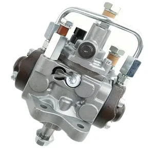
294000-1220 2940001220 for NISSAN YD25 DCi D40 NAVARA NV350 2.5L Fuel Pump 16700-5X00D 167005X00D
USD 431.35
13-05-2025
13-05-2025
HP3 common rail fuel pump 294000-1220 294000-2460 16700-4KV0A 16700-5X00A 16700-5X00B 16700-5X00D for Nissan Navara D40 2.5L
Images:
USD 380.32

[02-May-2025]
USD 461.67

[08-Jun-2025]
USD 461.67
[08-Jun-2025]
Components :
| 001. | PUMP ASSY, SUPPLY | 29400-01220 |
| 002. | OVERHAUL KIT, SUPP | 29400-90110 |
| 002. | OVERHAUL KIT, SUPP | 29400-90110 |
Scheme ###:
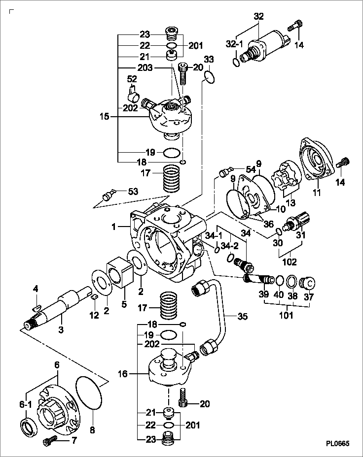
| 000. | [01] | 29400-01220 | PUMP ASSY, SUPPLY | 167005X00A |
| 001. | [01] | 29410-01390 | HOUSING SUB-ASSY, | HU |
| 002. | [02] | 29417-80040 | WASHER, CAMSHAFT | |
| 003. | [01] | 29419-10020 | CAMSHAFT, SUPPLY P | HU |
| 003. | [01] | 29419-10100 | CAMSHAFT, SUPPLY P | HU |
| 004. | [01] | 29402-10040 | KEY, WOODRUFF | |
| 004. | [01] | 29402-10020 | KEY, WOODRUFF | |
| 005. | [01] | 29417-00160 | RING SUB-ASSY, CAM | HU |
| 005. | [01] | 29417-00210 | RING SUB-ASSY, CAM | HU |
| 006. | [01] | 29412-00370 | COVER SUB-ASSY, BE | HU |
| 006. | [01] | 29412-00500 | COVER SUB-ASSY, BE | HU |
| 006-001. | [01] | 29419-70010 | SEAL, OIL | |
| 007. | [06] | 29419-90090 | BOLT, SOCKET | HU |
| 007. | [06] | 09644-90110 | BOLT, SOCKET | |
| 008. | [01] | 29419-80050 | O-RING, SUPPLY PUM | |
| 009. | [02] | 29419-80030 | O-RING, SUPPLY PUM | |
| 010. | [01] | 29418-30160 | PLATE, FEED PUMP, | |
| 011. | [01] | 29418-40170 | COVER, FEED PUMP | HU |
| 012. | [01] | 29418-70010 | KEY, FEED PUMP | |
| 012. | [01] | 29418-70040 | KEY, FEED PUMP | |
| 013. | [01] | 29418-00080 | ROTOR SET, FEED PU | HU |
| 014. | [05] | 09644-90050 | BOLT, SOCKET | |
| 014. | [05] | 29419-90080 | BOLT, SOCKET | HU |
| 015. | [01] | 29409-00290 | ELEMENT KIT, SUPPL | HU |
| 015. | [01] | 29409-00950 | ELEMENT KIT, SUPPL | HU |
| 016. | [01] | 29409-00300 | ELEMENT KIT, SUPPL | HU |
| 016. | [01] | 29409-00960 | ELEMENT KIT, SUPPL | HU |
| 017. | [02] | 29415-90040 | SPRING, PLUNGER | |
| 018. | [02] | 29419-80010 | O-RING, SUPPLY PUM | |
| 019. | [02] | 29419-80040 | O-RING, SUPPLY PUM | |
| 020. | [06] | 29419-90010 | BOLT, SOCKET | |
| 020. | [06] | 29419-90070 | BOLT, SOCKET | HU |
| 030. | [01] | 09806-60030 | O-RING, DISTRIBUTI | |
| 031. | [01] | 17973-00100 | SENSOR, FUEL TEMPE | |
| 032. | [01] | 29420-02760 | VALVE ASSY, SUCTIO | |
| 032. | [01] | 29420-00660 | VALVE ASSY, SUCTIO | |
| 032-001. | [01] | 29428-60010 | O-RING, VALVE | |
| 033. | [01] | 29428-50010 | O-RING, SOLENOID | |
| 034. | [01] | 29416-00110 | VALVE SUB-ASSY, RE | HU |
| 034. | [01] | 29416-00130 | VALVE SUB-ASSY, RE | HU |
| 034. | [01] | 29416-00200 | VALVE SUB-ASSY, RE | HU |
| 034-001. | [01] | 29419-80060 | O-RING, SUPPLY PUM | |
| 034-002. | [01] | 29419-80070 | O-RING, SUPPLY PUM | |
| 035. | [01] | 29401-00270 | PIPE, SUPPLY PUMP | HU |
| 036. | [02] | 29416-90010 | PIN, STOPPER | |
| 037. | [01] | 29411-50010 | PLUG, FILTER | |
| 038. | [01] | 09806-50030 | GASKET | HU |
| 039. | [01] | 09737-00010 | FILTER SUB-ASSY | |
| 040. | [01] | 09604-90460 | O-RING | |
| 052. | [01] | 09003-45250 | PLUG | HU |
| 053. | [01] | 09808-10060 | COVER, RUBBER | HU |
| 054. | [01] | 09808-10050 | COVER, RUBBER | HU |
| 101. | [01] | 29400-90010 | OVERHAUL KIT, SUPP | |
| 102. | [01] | 29400-90100 | OVERHAUL KIT, SUPP | |
| 200. | [01] | 29400-90110 | OVERHAUL KIT, SUPP |
Include in #3:
29400-01220
as PUMP ASSY, SUPPLY
Cross reference number
| Part num | Firm num | Firm | Name |
| 29400-01220 | 167005X00A | PUMP ASSY, SUPPLY | |
| 167005X00A | NISSAN MOTOR | PUMP ASSY SUPPLY |
Information:
2. Remove clamp (2) from water sleeves (1) in each cylinder head. Push the water sleeves into the timing gear cover with tool (A) and a screwdriver. 3. Remove bolt (3) from the bracket on the dipstick tube. 4. Remove bolts (4) and stud (5) from the heads.
Make sure the fuel injection nozzles are removed before the cylinder heads are removed. The fuel injection nozzles go through the cylinder heads and the nozzle tips can be broken off if the nozzles are not removed from the heads.
5. Install tooling (B) and fasten a hoist. Remove bolts (7), cylinder head (6) and the gasket. The weight of the cylinder head is 54 kg (120 lb.).Install Cylinder Heads
1. Clean the contact surfaces of the cylinder head and cylinder block. Make sure the surfaces are clean and dry. Install a new cylinder head gasket. Clean the bore in the cylinder head for the water sleeves. Put oil on the seals on the water sleeves.2. Install tooling (B) in the cylinder head. Fasten a hoist and put the cylinder head in position on the cylinder block.3. Put 6V4876 Molykote Lubricant on the bolt threads and install the bolts that hold the cylinder head in their correct location. Tighten the bolts in the cylinder head according to the HEAD BOLT TORQUE CHART.
The higher cylinder head bolt torque may be used on earlier engines ONLY if the bolts are replaced with the later higher strength bolts (seven dash marks on the bolt head). If the earlier bolts are tightened to the later torque specification, they may yield (stretch) and lose their clamping force.
4. Install water sleeve into cylinder head with tool (A). Install the clamp on the water sleeves.5. Fill the cooling system with coolant to the correct level. end by:a) install fuel injection nozzlesb) install rocker shafts and push rodsc) install valve coversd) install air inlet manifolde) install exhaust manifold
Illustration 1. Bolt head identification.Disassemble Cylinder Heads
start by: a) remove cylinder heads1. Fasten a hoist and put the cylinder head in position on tool (A). Use adapter plates (1) from tooling (A) to hold the head in place. 2. Put the valve springs under compression with tool (C). 3. Remove the locks from the valves. Earlier engines have an inner valve spring. Later engines have only one valve spring and a spacer instead of inner spring.4. Remove tool (C), retainer, spring, washer and valve from the cylinder head. Put identification on the valve as to its location in the cylinder head. 5. Check the valve spring force with tool (B). For the correct spring force, see the subject VALVES in SPECIFICATIONS.6. Do Steps 2 through 5 for the remainder of the valves.7. Remove the valve seat inserts with tooling (D). The valve guides are part of the cylinder head. Measure the bore in each valve guide 19.0 mm (.75 in.) from the outside edge on both ends of each valve guide. The bore must be 9.512 0.013 mm (.3745 .0005 in.). The