Information pump assy, supply
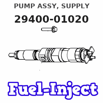
PUMP ASSY, SUPPLY
AA
- * DMHU DENSO PRODUCTION HU294000-102#
Rating:
You can express buy:
USD 530.33
19-05-2025
19-05-2025
2AD-FHV's remanufactured HP3 diesel common rail fuel pump 294000-1020 294000-1021 22100-0R050
USD 381.24
19-05-2025
19-05-2025
Engine Oil Pump Assembly fuel injection pump manufacturer 22100-0R050 294000-1020
USD 441
13-05-2025
13-05-2025
Engine Oil Pump Assembly fuel injection pump manufacturer 22100-0R050 294000-1020
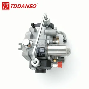
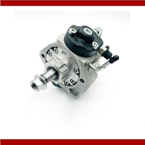
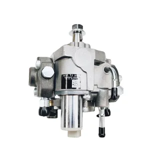
Images:
USD 395.21

[19-May-2025]
USD 391.16

[19-May-2025]
USD 534.1

[19-May-2025]
Components :
| 001. | PUMP ASSY, SUPPLY | 29400-01020 |
| 002. | OVERHAUL KIT, SUPP | 29400-90110 |
| 002. | OVERHAUL KIT, SUPP | 29400-90110 |
Scheme ###:
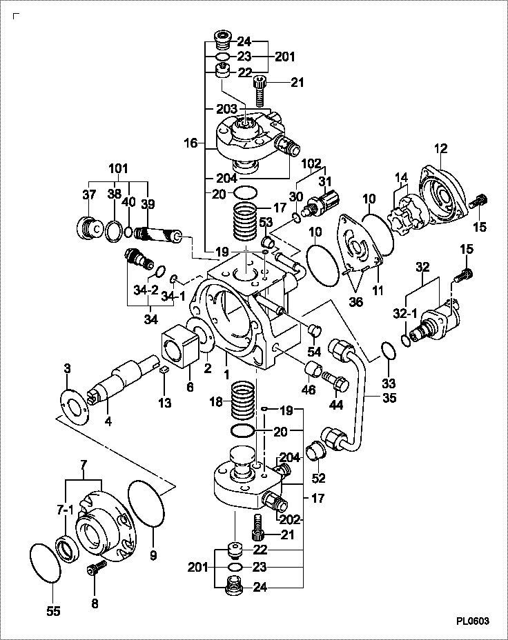
| 000. | [01] | 29400-01020 | PUMP ASSY, SUPPLY | 22100-0R050 |
| 001. | [01] | 29410-01250 | HOUSING SUB-ASSY, | HU |
| 002. | [01] | 29417-80040 | WASHER, CAMSHAFT | |
| 003. | [01] | 29417-80080 | WASHER, CAMSHAFT | |
| 004. | [01] | 29419-10070 | CAMSHAFT, SUPPLY P | HU |
| 006. | [01] | 29417-00210 | RING SUB-ASSY, CAM | HU |
| 006. | [01] | 29417-00160 | RING SUB-ASSY, CAM | HU |
| 007. | [01] | 29412-00350 | COVER SUB-ASSY, BE | HU |
| 007. | [01] | 29412-00440 | COVER SUB-ASSY, BE | HU |
| 007-001. | [01] | 29419-70020 | SEAL, OIL | |
| 008. | [06] | 09644-90110 | BOLT, SOCKET | 22395-56351 |
| 008. | [06] | 29419-90090 | BOLT, SOCKET | HU |
| 009. | [01] | 29419-80050 | O-RING, SUPPLY PUM | |
| 010. | [02] | 29419-80030 | O-RING, SUPPLY PUM | |
| 011. | [01] | 29418-30160 | PLATE, FEED PUMP, | |
| 012. | [01] | 29418-40050 | COVER, FEED PUMP | HU |
| 012. | [01] | 29418-40170 | COVER, FEED PUMP | HU |
| 013. | [01] | 29418-70010 | KEY, FEED PUMP | |
| 013. | [01] | 29418-70040 | KEY, FEED PUMP | |
| 014. | [01] | 29418-00080 | ROTOR SET, FEED PU | HU |
| 015. | [05] | 29419-90080 | BOLT, SOCKET | HU |
| 015. | [05] | 09644-90050 | BOLT, SOCKET | 22395-54270 |
| 016. | [01] | 29409-00500 | ELEMENT KIT, SUPPL | HU |
| 017. | [01] | 29409-00490 | ELEMENT KIT, SUPPL | HU |
| 018. | [02] | 29415-90040 | SPRING, PLUNGER | |
| 019. | [02] | 29419-80010 | O-RING, SUPPLY PUM | |
| 020. | [02] | 29419-80040 | O-RING, SUPPLY PUM | |
| 021. | [06] | 29419-90010 | BOLT, SOCKET | |
| 021. | [06] | 29419-90070 | BOLT, SOCKET | HU |
| 030. | [01] | 09806-60030 | O-RING, DISTRIBUTI | 22193-1C170 |
| 031. | [01] | 17973-00100 | SENSOR, FUEL TEMPE | 89454-20010 |
| 032. | [01] | 29420-00610 | VALVE ASSY, SUCTIO | |
| 032-001. | [01] | 29428-60010 | O-RING, VALVE | |
| 033. | [01] | 29428-50010 | O-RING, SOLENOID | |
| 034. | [01] | 29416-00100 | VALVE SUB-ASSY, RE | HU |
| 034. | [01] | 29416-00220 | VALVE SUB-ASSY, RE | HU |
| 034-001. | [01] | 29419-80060 | O-RING, SUPPLY PUM | |
| 034-002. | [01] | 29419-80070 | O-RING, SUPPLY PUM | |
| 035. | [01] | 29401-00170 | PIPE, SUPPLY PUMP | HU |
| 036. | [02] | 29416-90010 | PIN, STOPPER | |
| 037. | [01] | 29411-50010 | PLUG, FILTER | |
| 038. | [01] | 09806-50030 | GASKET | HU |
| 039. | [01] | 09737-00010 | FILTER SUB-ASSY | |
| 040. | [01] | 09604-90460 | O-RING | 22193-5B320 |
| 043. | [01] | 09543-80130 | SCREW, HOLLOW | HU |
| 044. | [01] | 94919-80420 | COLLAR, PRESSBOARD | |
| 052. | [01] | 09003-45250 | PLUG | HU |
| 053. | [01] | 09808-10050 | COVER, RUBBER | HU |
| 054. | [01] | 09808-10060 | COVER, RUBBER | HU |
| 055. | [01] | 29419-80260 | O-RING, SUPPLY PUM | 22193-0R020 |
| 101. | [01] | 29400-90010 | OVERHAUL KIT, SUPP | |
| 102. | [01] | 29400-90100 | OVERHAUL KIT, SUPP | |
| 200. | [01] | 29400-90110 | OVERHAUL KIT, SUPP |
Include in #3:
29400-01020
as PUMP ASSY, SUPPLY
Cross reference number
| Part num | Firm num | Firm | Name |
| 29400-01020 | 22100-0R05 | PUMP ASSY, SUPPLY | |
| 22100-0R050 | TOYOTA | PUMP ASSY SUPPLY |
Information:
1. Position the water pump on the engine.2. Connect the water temperature regulator bypass line.3. Connect water pump outlet line.concluding step: a) install air compressorDisassemble Water Pump
preparatory step: a) remove water pump 1. Remove the water pump cover (1). 2. Loosen the impeller retaining nut flush with the end of the pump shaft. Install tool setup (A) and separate the impeller from the shaft.3. Remove the tool setup and impeller. 4. Remove the bearing cage retaining nuts (3).5. Remove the bearing cage and shaft assembly (2) from the pump housing.6. Remove the ceramic seal and oil seal from the pump housing.7. Remove the bearing retaining nut and spacer from the shaft assembly. 8. Press the gear and bearings from the shaft.Assemble Water Pump
1. Heat the bearings and gear to 300°F (149°C). 2. Install one bearing and its bearing cage (5) on the shaft. Install the gear (4) on the shaft with the concave side towards the bearing cage.3. Install the remaining bearing (3), spacer (2), lock and retaining nut (1). 4. Install the oil seal in the pump housing using tool setup (A). Install the oil seal (8) as shown. 5. Install the ceramic ring (11) and rubber seal (12) in the pump housing with the polished side of the ceramic ring toward the impeller.6. Position the bearing and shaft assembly in the pump housing. Install the bearing cage retaining nuts (7). Lubricate the oil seal lip lightly with SAE 30 engine oil before installing the shaft assembly.7. Install the carbon portion of the seal and the spring on the shaft.8. Install the impeller (10) and retaining nut (6). Tighten the nut to 30 5 lb. ft. (4,1 0,7 mkg) plus the amount required to align on cotter pin hole. Install the cotter pin and bend the legs of the pin around the nut.9. Install the water pump cover (9).concluding step: a) install water pump