Information pump assy, supply
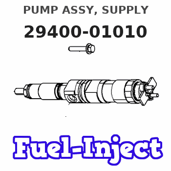
PUMP ASSY, SUPPLY
BA
- * DMHU DENSO PRODUCTION HU294000-101#
Rating:
Compare Prices: .
As an associate, we earn commssions on qualifying purchases through the links below

Fuel Injection Pump 294000-1010 8-98092467-0 for Opel Engine A17DT A17DTJ Z17DTR A17DTR
ADPelcote Part number:294000-1010 || Applications:for Opel Engine A17DT A17DTJ Z17DTR A17DTR
ADPelcote Part number:294000-1010 || Applications:for Opel Engine A17DT A17DTJ Z17DTR A17DTR

Fuel Injection Pump 294000-1010 8-98092467-0 for Opel Engine A17DT A17DTJ Z17DTR A17DTR
SEBAOFADANSIOS Part Number: 294000-1010, 8-98092467-0, 2940001010, 8980924670 || Application:for Opel Engine A17DT A17DTJ Z17DTR A17DTR
SEBAOFADANSIOS Part Number: 294000-1010, 8-98092467-0, 2940001010, 8980924670 || Application:for Opel Engine A17DT A17DTJ Z17DTR A17DTR

You can express buy:

USD 35.53
10-11-2022
10-11-2022
USD 32.35
06-11-2018
06-11-2018
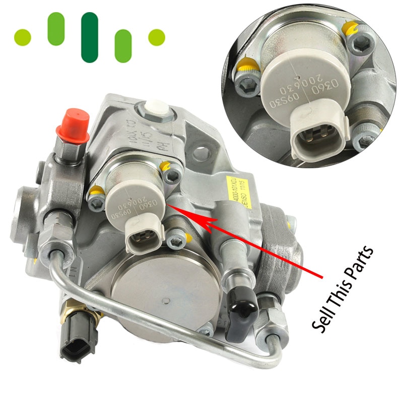
Fuel Pressure Suction Control SCV Valve 294200-0360 Used on Recovered Denso Diesel Fuel Pump 294000-1010 DCRP301010 294000-101#
Components :
| 001. | PUMP ASSY, SUPPLY | 29400-01010 |
| 002. | OVERHAUL KIT, SUPP | 29400-90110 |
| 002. | OVERHAUL KIT, SUPP | 29400-90110 |
Scheme ###:
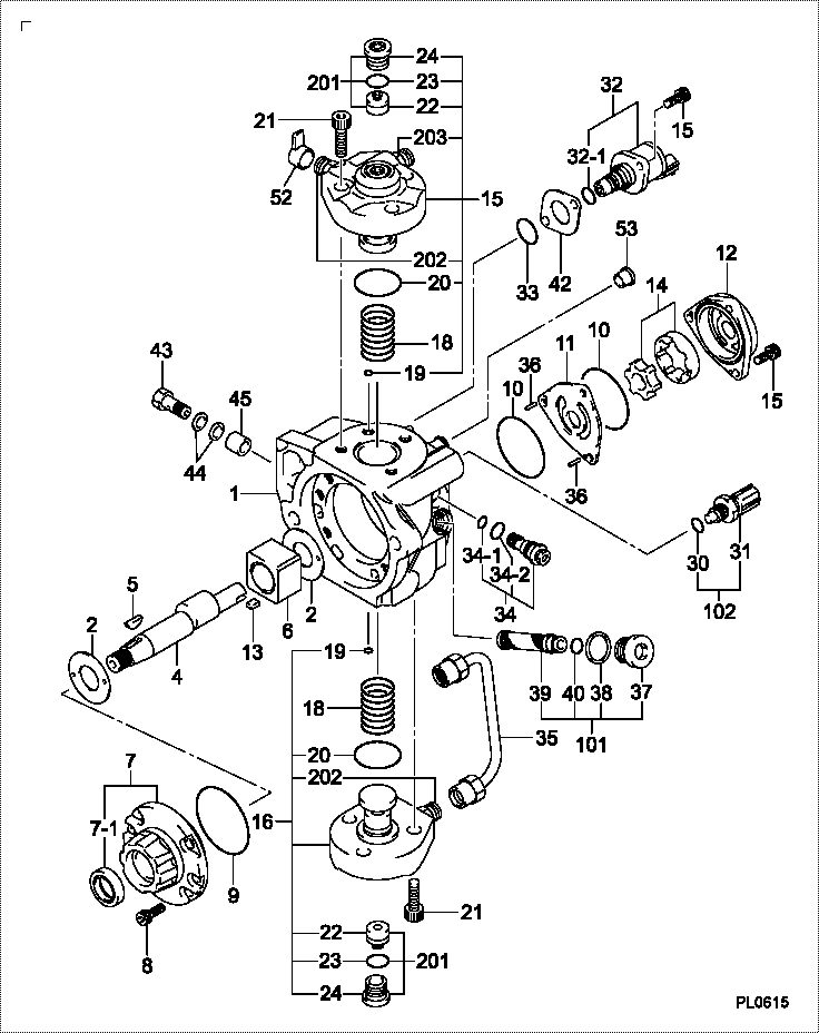
| 000. | [01] | 29400-01010 | PUMP ASSY, SUPPLY | 8-98092467-0 |
| 001. | [01] | 29410-01240 | HOUSING SUB-ASSY, | H-U |
| 002. | [02] | 29417-80040 | WASHER, CAMSHAFT | |
| 004. | [01] | 29419-10020 | CAMSHAFT, SUPPLY P | H-U |
| 005. | [01] | 29402-10020 | KEY, WOODRUFF | |
| 006. | [01] | 29417-00160 | RING SUB-ASSY, CAM | H-U |
| 007. | [01] | 29412-00370 | COVER SUB-ASSY, BE | H-U |
| 007-001. | [01] | 29419-70010 | SEAL, OIL | |
| 008. | [06] | 09644-90110 | BOLT, SOCKET | 8-97140853-0 |
| 008. | [06] | 29419-90090 | BOLT, SOCKET | H-U |
| 009. | [01] | 29419-80050 | O-RING, SUPPLY PUM | |
| 010. | [02] | 29419-80030 | O-RING, SUPPLY PUM | |
| 011. | [01] | 29418-30160 | PLATE, FEED PUMP, | |
| 012. | [01] | 29418-40170 | COVER, FEED PUMP | H-U |
| 013. | [01] | 29418-70010 | KEY, FEED PUMP | |
| 013. | [01] | 29418-70040 | KEY, FEED PUMP | |
| 014. | [01] | 29418-00080 | ROTOR SET, FEED PU | H-U |
| 015. | [05] | 09644-90050 | BOLT, SOCKET | |
| 015. | [05] | 29419-90080 | BOLT, SOCKET | H-U |
| 016. | [01] | 29409-00960 | ELEMENT KIT, SUPPL | H-U |
| 016. | [01] | 29409-00300 | ELEMENT KIT, SUPPL | H-U |
| 017. | [01] | 29409-00290 | ELEMENT KIT, SUPPL | H-U |
| 017. | [01] | 29409-00950 | ELEMENT KIT, SUPPL | H-U |
| 018. | [02] | 29415-90040 | SPRING, PLUNGER | |
| 019. | [02] | 29419-80010 | O-RING, SUPPLY PUM | |
| 020. | [02] | 29419-80040 | O-RING, SUPPLY PUM | |
| 021. | [06] | 29419-90070 | BOLT, SOCKET | H-U |
| 021. | [06] | 29419-90010 | BOLT, SOCKET | |
| 030. | [01] | 09806-60030 | O-RING, DISTRIBUTI | |
| 031. | [01] | 17973-00100 | SENSOR, FUEL TEMPE | 8-98023581-0 |
| 032. | [01] | 29420-00360 | VALVE ASSY, SUCTIO | S-M |
| 032. | [01] | 29420-00460 | VALVE ASSY, SUCTIO | S-M |
| 032-001. | [01] | 29428-60030 | O-RING, VALVE | S-M |
| 033. | [01] | 29428-50040 | O-RING, SOLENOID | |
| 034. | [01] | 29416-00110 | VALVE SUB-ASSY, RE | H-U |
| 034-001. | [01] | 29419-80060 | O-RING, SUPPLY PUM | |
| 034-002. | [01] | 29419-80070 | O-RING, SUPPLY PUM | |
| 035. | [01] | 29401-00071 | PIPE, SUPPLY PUMP | S-M |
| 036. | [02] | 29416-90010 | PIN, STOPPER | |
| 037. | [01] | 29411-50010 | PLUG, FILTER | |
| 038. | [01] | 09806-50030 | GASKET | H-U |
| 039. | [01] | 09737-00010 | FILTER SUB-ASSY | |
| 040. | [01] | 09604-90460 | O-RING | |
| 042. | [01] | 29425-90020 | GASKET, SOLENOID | |
| 043. | [01] | 29404-10040 | SCREW, HOLLOW, SUP | H-U |
| 044. | [02] | 94901-02470 | WASHER | 1-15619508-0 |
| 045. | [01] | 94919-80260 | COLLAR, PRESSBOARD | |
| 052. | [01] | 09003-45250 | PLUG | |
| 053. | [01] | 09808-10050 | COVER, RUBBER | |
| 101. | [01] | 29400-90010 | OVERHAUL KIT, SUPP | |
| 102. | [01] | 29400-90100 | OVERHAUL KIT, SUPP | |
| 200. | [01] | 29400-90110 | OVERHAUL KIT, SUPP |
Include in #3:
29400-01010
as PUMP ASSY, SUPPLY
Cross reference number
| Part num | Firm num | Firm | Name |
| 29400-01010 | 8-98092467 | PUMP ASSY, SUPPLY | |
| 8-98092467-0 | ISUZU | PUMP ASSY SUPPLY |
Information:
preparatory step: a) separate governor from fuel injection pump housing. 1. Remove the fuel injection pump as follows: a) Remove the protective cap and the felt washer (1). b) Install wrench (A) and remove retaining bushing (2) from housing.c) Remove the seal (3). d) Install extractor (B).e) Lift the fuel injection pump out of the housing.f) Remove the spacer (4). Keep the spacers (4) and pumps together, and identified as to their location in the fuel injection pump housing.2. Disassemble the fuel injection pumps as follows: a) Remove the bonnet (5), ring (6), spring (7), and check valve (8) from the barrel (9).b) Remove the plunger assembly (10), washer (11), and spring (12) from the barrel (9).
While disassembling and assembling fuel injection pump, exercise considerable care to prevent damage to plunger surfaces. The barrel and plunger assemblies are matched, and the individual parts are not interchangeable with other barrels or plunger assemblies.
3. Remove the rack (13).4. Remove the lifters (14). Keep the lifters identified and together with their respective pumps and spacers. 5. Remove the camshaft retaining plate (15), bolt and lock. 6. Remove the spring (16) and the gear assembly (17) from the camshaft. 7. Remove the camshaft (19). 8. Using tool (C), remove the camshaft bearings from the fuel injection pump housing.9. Remove the two rack bearings (18) from the fuel injection pump housing.Assemble Fuel Injection Pump Housing
1. Using tool group (C), install the camshaft bearings in the fuel injection pump housing. Install the bearing in governor end of housing so the oil hole in bearing is aligned with oil hole in housing. Install the camshaft bearings flush with outer ends of fuel injection pump housing. 2. Using tool (D), install the two rack bearings in the fuel injection pump housing. Install the bearing in governor end of housing so it will be recessed .195 .005 in. (4,953 0,127 mm) from face of housing. Install the rack bearing in accessory drive end of housing so it will be flush with face of fuel injection pump housing. 3. Lubricate the camshaft with clean SAE 30 engine oil. Install the camshaft in fuel injection pump housing. 4. Postion the governor drive gear (1) and spring (2) on the camshaft. Install the camshaft retaining plate (3), bolt, and lock. 5. Install the lifters (4) in their respective positions in housing. Lubricate the rack generously with clean SAE 30 engine oil. Install the rack (5) into fuel injection pump housing with the slot in rack toward the governor end of housing.6. Install the spacers in their respective positions in housing. If new lifters and pumps are to be installed, it will be necessary to set the fuel pump timing dimension. See FUEL INJECTION PUMP TIMING DIMENSION SETTING-OFF ENGINE in TESTING AND ADJUSTING.7. Assemble the fuel injection pumps as follows: a) Lubricate all parts generously with clean fuel oil.b) Install the spring, washer, and plunger in the barrel.c) Install the spring, check valve, bonnet, and ring on the barrel.
Do