Information pump assy, supply
PUMP ASSY, SUPPLY
AA
- * DMHU DENSO PRODUCTION HU294000-088#
- #1..CHANGE OVER DATE UNSCHEDULED.
- #2 IS A HOUSING KIT FOR CONVERSION TO HU294000-1570.

Rating:
Compare Prices: .
As an associate, we earn commssions on qualifying purchases through the links below

Compatible with New Holland Engine T4 T5 3.2L 3.4L 2012-2017 Fuel Injection Pump 0445020508 0445020516 5801470100
KoovDem Part Number:294000-0880 2940000880 || Part Name: Fuel Injection Pump || The Ford 2.3L EcoBoost engine is a powerful and dependable option prized for its strong performance, minimal emissions, and fuel efficiency. This engine features cutting-edge technology such as turbocharging and direct fuel injection for seamless power output and exceptional fuel economy. With its robust build and innovative engineering, it is a popular selection for environmentally conscious vehicles that prioritize performance. || Compatible with Toyota's 2AD-FHV diesel engine. || The package includes one Fuel Injection Pump, specifically the model number 294000-0880 (2940000880).
KoovDem Part Number:294000-0880 2940000880 || Part Name: Fuel Injection Pump || The Ford 2.3L EcoBoost engine is a powerful and dependable option prized for its strong performance, minimal emissions, and fuel efficiency. This engine features cutting-edge technology such as turbocharging and direct fuel injection for seamless power output and exceptional fuel economy. With its robust build and innovative engineering, it is a popular selection for environmentally conscious vehicles that prioritize performance. || Compatible with Toyota's 2AD-FHV diesel engine. || The package includes one Fuel Injection Pump, specifically the model number 294000-0880 (2940000880).
Components :
| 001. | PUMP ASSY, SUPPLY | 29400-00880 |
| 002. | OVERHAUL KIT, SUPP | 29400-90110 |
| 002. | OVERHAUL KIT, SUPP | 29400-90110 |
| 003. | OVERHAUL KIT, SUPP | 29400-91450 |
Scheme ###:
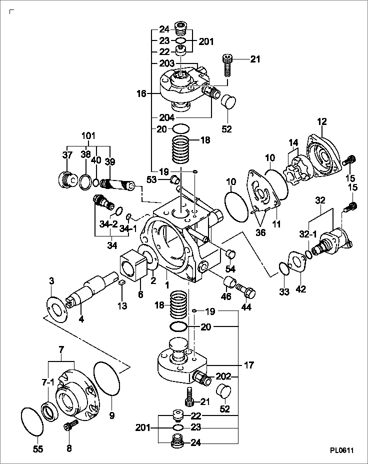
| 000. | [01] | 29400-00880 | PUMP ASSY, SUPPLY | 22100-0R031 |
| 001. | [01] | 29410-00402 | HOUSING SUB-ASSY, | HU |
| 002. | [01] | 29417-80040 | WASHER, CAMSHAFT | |
| 003. | [01] | 29417-80080 | WASHER, CAMSHAFT | |
| 004. | [01] | 29419-10070 | CAMSHAFT, SUPPLY P | HU |
| 006. | [01] | 29417-00160 | RING SUB-ASSY, CAM | HU |
| 006. | [01] | 29417-00190 | RING SUB-ASSY, CAM | HU |
| 007. | [01] | 29412-00350 | COVER SUB-ASSY, BE | HU |
| 007. | [01] | 29412-00440 | COVER SUB-ASSY, BE | HU |
| 007-001. | [01] | 29419-70020 | SEAL, OIL | |
| 008. | [06] | 09644-90110 | BOLT, SOCKET | 22395-56351 |
| 008. | [06] | 29419-90090 | BOLT, SOCKET | HU |
| 009. | [01] | 29419-80050 | O-RING, SUPPLY PUM | |
| 010. | [02] | 29419-80030 | O-RING, SUPPLY PUM | |
| 011. | [01] | 29418-30160 | PLATE, FEED PUMP, | |
| 012. | [01] | 29418-40050 | COVER, FEED PUMP | HU |
| 012. | [01] | 29418-40170 | COVER, FEED PUMP | HU |
| 013. | [01] | 29418-70010 | KEY, FEED PUMP | |
| 014. | [01] | 29418-00080 | ROTOR SET, FEED PU | HU |
| 015. | [05] | 09644-90050 | BOLT, SOCKET | 22395-54270 |
| 015. | [05] | 29419-90080 | BOLT, SOCKET | HU |
| 016. | [01] | 29409-00070 | ELEMENT KIT, SUPPL | HU |
| 017. | [01] | 29409-00210 | ELEMENT KIT, SUPPL | HU |
| 018. | [02] | 29415-90040 | SPRING, PLUNGER | |
| 019. | [02] | 29419-80010 | O-RING, SUPPLY PUM | |
| 020. | [02] | 29419-80040 | O-RING, SUPPLY PUM | |
| 021. | [06] | 29419-90010 | BOLT, SOCKET | |
| 021. | [06] | 29419-90070 | BOLT, SOCKET | HU |
| 032. | [01] | 29420-00310 | VALVE ASSY, SUCTIO | SM |
| 032-001. | [01] | 29428-60030 | O-RING, VALVE | SM |
| 033. | [01] | 29428-50040 | O-RING, SOLENOID | |
| 034. | [01] | 29416-00100 | VALVE SUB-ASSY, RE | HU |
| 034-001. | [01] | 29419-80060 | O-RING, SUPPLY PUM | |
| 034-002. | [01] | 29419-80070 | O-RING, SUPPLY PUM | |
| 036. | [02] | 29416-90010 | PIN, STOPPER | |
| 037. | [01] | 29411-50010 | PLUG, FILTER | |
| 038. | [01] | 09806-50030 | GASKET | HU |
| 039. | [01] | 09737-00010 | FILTER SUB-ASSY | |
| 040. | [01] | 09604-90460 | O-RING | 22193-5B320 |
| 042. | [01] | 29425-90020 | GASKET, SOLENOID | |
| 044. | [01] | 09543-80130 | SCREW, HOLLOW | |
| 046. | [01] | 94919-80420 | COLLAR, PRESSBOARD | |
| 052. | [02] | 09003-45250 | PLUG | HU |
| 053. | [01] | 09808-10050 | COVER, RUBBER | HU |
| 054. | [01] | 09808-10060 | COVER, RUBBER | HU |
| 055. | [01] | 29419-80260 | O-RING, SUPPLY PUM | 22193-0R020 |
| 101. | [01] | 29400-90010 | OVERHAUL KIT, SUPP | |
| 200. | [01] | 29400-90110 | OVERHAUL KIT, SUPP | |
| 201. | [01] | 29400-91450 | OVERHAUL KIT, SUPP | HU |
Include in #3:
29400-00880
as PUMP ASSY, SUPPLY
Cross reference number
| Part num | Firm num | Firm | Name |
| 29400-00880 | 22100-0R03 | PUMP ASSY, SUPPLY | |
| 22100-0R031 | TOYOTA | PUMP ASSY SUPPLY |
Information:
1. Disconnect the fuel ratio control sensing line (1). Remove the sensing line clamp bolt (2).2. Disconnect the air compressor water return line (6). 3. Remove the cylinder head air inlet line (3).4. Remove the retaining bolts (4) and the fan drive mounting bracket (5).5. Remove the cylinder head retaining bolts. Attach a hoist and remove the cylinder head assembly - weight 164 lbs. (74,4 kg).Install Cylinder Head
1. Thoroughly clean the sealing surfaces of the cylinder head and cylinder block. Position a new head gasket on the engine and install the cylinder head.2. Install the push rods and rocker shaft assembly.3. Coat the threads of the cylinder head retaining bolts with 4S9416 Anti-Seize Compound. Install bolts and washers, and tighten them in the following sequence: 1 - Tighten all numbered bolts in numerical order to 115 lb. ft. (15,9 mkg).2 - Retighten all numbered bolts in numerical order to 175 5 lb. ft. (24,2 0,7 mkg).3 - Finally, retighten all numbered bolts (hand torque only) in numerical order to 175 5 lb. ft. (24,2 0,7 mkg).4 - Tighten all lettered bolts in alphabetical order to 22 lb. ft. (3,0 mkg).5 - Retighten all lettered bolts in alphabetical order to 32 5 lb. ft. (4,4 0,7 mkg).6 - Finally, retighten all lettered bolts (hand torque only) in alphabetical order to 32 5 lb. ft. (4,4 0,7 mkg).4. Adjust the inlet and exhaust valve clearance as covered in INSTALL ROCKER SHAFT ASSEMBLY AND PUSH RODS.5. Connect the air compressor water return line.6. Connect the fuel ratio control sensing line and install the sensing line clamp bolt.7. Install the fan drive mounting bracket and retaining bolts.concluding steps: a) install water temperature regulatorb) install valve coverc) install precombustion chambersd) install exhaust manifold
1. Thoroughly clean the sealing surfaces of the cylinder head and cylinder block. Position a new head gasket on the engine and install the cylinder head.2. Install the push rods and rocker shaft assembly.3. Coat the threads of the cylinder head retaining bolts with 4S9416 Anti-Seize Compound. Install bolts and washers, and tighten them in the following sequence: 1 - Tighten all numbered bolts in numerical order to 115 lb. ft. (15,9 mkg).2 - Retighten all numbered bolts in numerical order to 175 5 lb. ft. (24,2 0,7 mkg).3 - Finally, retighten all numbered bolts (hand torque only) in numerical order to 175 5 lb. ft. (24,2 0,7 mkg).4 - Tighten all lettered bolts in alphabetical order to 22 lb. ft. (3,0 mkg).5 - Retighten all lettered bolts in alphabetical order to 32 5 lb. ft. (4,4 0,7 mkg).6 - Finally, retighten all lettered bolts (hand torque only) in alphabetical order to 32 5 lb. ft. (4,4 0,7 mkg).4. Adjust the inlet and exhaust valve clearance as covered in INSTALL ROCKER SHAFT ASSEMBLY AND PUSH RODS.5. Connect the air compressor water return line.6. Connect the fuel ratio control sensing line and install the sensing line clamp bolt.7. Install the fan drive mounting bracket and retaining bolts.concluding steps: a) install water temperature regulatorb) install valve coverc) install precombustion chambersd) install exhaust manifold