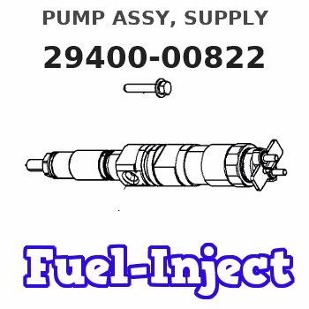
Information pump assy, supply
Rating:
Compare Prices: .
As an associate, we earn commssions on qualifying purchases through the links below

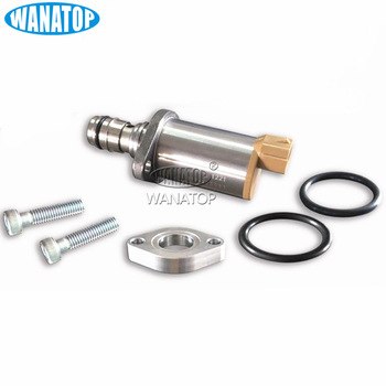
High Pressure Fuel Pump Regulator Suction Control SCV Valve For ISUZU 4HJ1 4HK1 6HK1 D-MAX ElF 294200-0650 0050 8-98043687-0 - (Style: A, Color: 294000-0822)
Generic Color: 294000-0822
Generic Color: 294000-0822
SCV control valve 8-98043687-0 294200-0650 294000-0290 294000-0294 294000-0822 For ISUZU D-MAX - (Color: 294000-0822)
Generic Color: 294000-0822
Generic Color: 294000-0822
You can express buy:

USD 58
13-05-2025
13-05-2025
Fuel Pump Suction Control Valve 294200-0270 294000-0290 294000-0294 294000-0822 04226-E0040 04226-E0030 294000-0291 294000-0292
USD 58
11-11-2022
11-11-2022
Components :
| 001. | PUMP ASSY, SUPPLY | 29400-00822 |
| 002. | OVERHAUL KIT, SUPP | 29400-90031 |
Scheme ###:
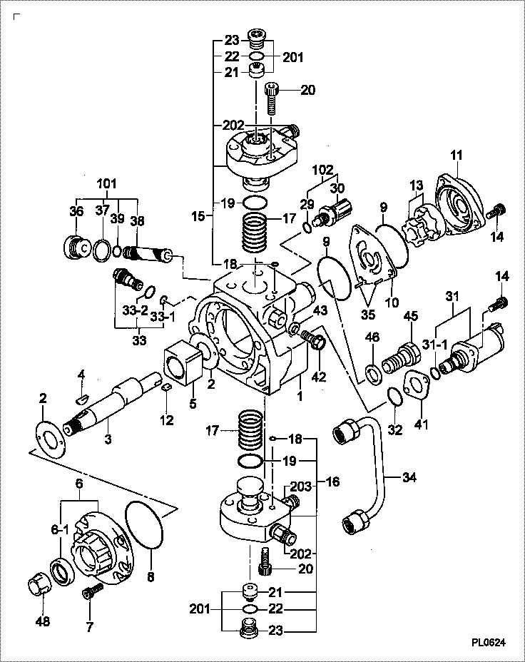
| 000. | [01] | 29400-00822 | PUMP ASSY, SUPPLY | |
| 001. | [01] | 29410-00441 | HOUSING SUB-ASSY, | |
| 001. | [01] | 29410-01100 | HOUSING SUB-ASSY, | |
| 002. | [02] | 29417-80040 | WASHER, CAMSHAFT | |
| 003. | [01] | 29419-10010 | CAMSHAFT, SUPPLY P | |
| 003. | [01] | 29419-10080 | CAMSHAFT, SUPPLY P | |
| 004. | [01] | 29402-10020 | KEY, WOODRUFF | 3313345700 |
| 004. | [01] | 29402-10040 | KEY, WOODRUFF | |
| 005. | [01] | 29417-00210 | RING SUB-ASSY, CAM | |
| 005. | [01] | 29417-00120 | RING SUB-ASSY, CAM | |
| 005. | [01] | 29417-00010 | RING SUB-ASSY, CAM | |
| 006. | [01] | 29412-00021 | COVER SUB-ASSY, BE | |
| 006. | [01] | 29412-00270 | COVER SUB-ASSY, BE | |
| 006. | [01] | 29412-00310 | COVER SUB-ASSY, BE | |
| 006-001. | [01] | 29419-70010 | SEAL, OIL | |
| 007. | [06] | 09644-90110 | BOLT, SOCKET | |
| 008. | [01] | 29419-80050 | O-RING, SUPPLY PUM | |
| 009. | [02] | 29419-80030 | O-RING, SUPPLY PUM | |
| 010. | [01] | 29418-30040 | PLATE, FEED PUMP, | |
| 010. | [01] | 29418-30170 | PLATE, FEED PUMP, | |
| 011. | [01] | 29418-40140 | COVER, FEED PUMP | |
| 012. | [01] | 29418-70010 | KEY, FEED PUMP | |
| 012. | [01] | 29418-70040 | KEY, FEED PUMP | |
| 013. | [01] | 29418-00010 | ROTOR SET, FEED PU | |
| 013. | [01] | 29418-00080 | ROTOR SET, FEED PU | |
| 014. | [05] | 09644-90050 | BOLT, SOCKET | |
| 015. | [01] | 29409-00040 | ELEMENT KIT, SUPPL | |
| 015. | [01] | 29409-00800 | ELEMENT KIT, SUPPL | |
| 016. | [01] | 29409-00030 | ELEMENT KIT, SUPPL | |
| 016. | [01] | 29409-00850 | ELEMENT KIT, SUPPL | |
| 017. | [02] | 29415-90040 | SPRING, PLUNGER | |
| 018. | [02] | 29419-80010 | O-RING, SUPPLY PUM | |
| 019. | [02] | 29419-80040 | O-RING, SUPPLY PUM | |
| 020. | [06] | 29419-90010 | BOLT, SOCKET | |
| 029. | [01] | 09806-60030 | O-RING, DISTRIBUTI | |
| 030. | [01] | 17973-00020 | SENSOR, FUEL TEMPE | |
| 030. | [01] | 17973-00100 | SENSOR, FUEL TEMPE | |
| 031. | [01] | 29420-00110 | VALVE ASSY, SUCTIO | |
| 031. | [01] | 29420-00170 | VALVE ASSY, SUCTIO | |
| 031. | [01] | 29420-00270 | VALVE ASSY, SUCTIO | |
| 031. | [01] | 29420-00650 | VALVE ASSY, SUCTIO | |
| 031-001. | [01] | 29428-60030 | O-RING, VALVE | |
| 032. | [01] | 29428-50010 | O-RING, SOLENOID | |
| 032. | [01] | 29428-50040 | O-RING, SOLENOID | |
| 033. | [01] | 29416-00011 | VALVE SUB-ASSY, RE | |
| 033. | [01] | 29416-00130 | VALVE SUB-ASSY, RE | |
| 033-001. | [01] | 29419-80060 | O-RING, SUPPLY PUM | |
| 033-002. | [01] | 29419-80070 | O-RING, SUPPLY PUM | |
| 034. | [01] | 29401-00021 | PIPE, SUPPLY PUMP | |
| 035. | [02] | 29416-90010 | PIN, STOPPER | |
| 036. | [01] | 29411-50010 | PLUG, FILTER | |
| 037. | [01] | 29411-70010 | GASKET, PLUG | |
| 038. | [01] | 09737-00010 | FILTER SUB-ASSY | |
| 039. | [01] | 09604-90460 | O-RING | |
| 041. | [01] | 29425-90020 | GASKET, SOLENOID | |
| 042. | [01] | 09543-80010 | SCREW, HOLLOW | 3313745700 |
| 042. | [01] | 09543-80170 | SCREW, HOLLOW | |
| 043. | [02] | 94901-02530 | WASHER | |
| 044. | [01] | 29409-90010 | COLLAR, FUEL OUTLE | |
| 045. | [01] | 94918-00310 | SCREW, HOLLOW | 3313645700 |
| 046. | [02] | 94901-02490 | WASHER | |
| 047. | [01] | 94919-80270 | COLLAR, PRESSBOARD | |
| 048. | [01] | 94905-62390 | NUT | 3313245700 |
| 052. | [01] | 09001-40160 | CAP, VALVE HOLDER | |
| 101. | [01] | 29400-90010 | OVERHAUL KIT, SUPP | |
| 102. | [01] | 29400-90020 | OVERHAUL KIT, SUPP | |
| 200. | [01] | 29400-90031 | OVERHAUL KIT, SUPP |
Include in #3:
29400-00822
as PUMP ASSY, SUPPLY
Cross reference number
| Part num | Firm num | Firm | Name |
| 29400-00822 | PUMP ASSY, SUPPLY |
Information:
EXHAUST MANIFOLD
1. Locks (four each side). 2. Retaining bolts (eight each side). 3. Exhaust manifold (one each side).Install Exhaust Manifold
1. Clean the exhaust manifold gasket mounting surfaces.2. Position the gasket and exhaust manifold on the engine and install the retaining bolts with locks. Tighten retaining bolts to 32 5 lb. ft. (4.4 0.7 mkg). Bend tabs on locks over flats of retaining bolt heads. Lock tabs must be bent over flats of retaining bolt heads. If necessary to align flats, tighten bolts a maximum additional turn of 30°. Do not loosen bolts to align flats.Disassemble Crankcase Ventilation Valve
1. Remove screws (2) that hold cover (3) on housing (1).
VENTILATION VALVE
1. Housing. 2. Screws (seven). 3. Cover.2. Remove cover (3) and spring (4).
REMOVING COVER
1. Housing. 3. Cover. 4. Spring.3. Remove the piston, sleeve (8), retainer (9), and diaphragm (7) from housing (1) as a unit. Remove inner sleeve (6) and gasket (5) from housing (1).
DISASSEMBLING VALVE
1. Housing. 5. Gasket. 6. Inner sleeve. 7. Diaphragm. 8. Sleeve. 9. Retainer.4. Remove nut (12), washer (13), spacer (11), piston (10), diaphragm (7), and the retainer from sleeve (8).
REMOVING DIAPHRAGM
7. Diaphragm. 8. Sleeve. 10. Piston. 11. Spacer. 12. Nut. 13. Washer.Assemble Crankcase Ventilation Valve
1. Put 5H2471 Gasket Cement on both sides of gasket (5) and install the gasket on housing (1). Install inner sleeve (6) in housing (1).2. Inspect diaphragm (7) for damage. Put piston (10) against side of diaphragm (7) that is stamped "piston side" and put retainer (9) in diaphragm (7).
INSTALLING INNER SLEEVE
1. Housing. 5. Gasket. 6. Inner sleeve.
ASSEMBLING DIAPHRAGM
7. Diaphragm. 9. Retainer. 10. Piston.3. Put the screw through sleeve (8), retainer (9), diaphragm (7), and piston (10). Put spacer (11), washer (13), and nut (12) on the screw and tighten the nut.
ASSEMBLING DIAPHRAGM
7. Diaphragm. 8. Sleeve. 10. Piston. 11. Spacer. 12. Nut. 13. Washer.4. Put 5H2471 Gasket Cement on both sides of the diaphragm (7) to prevent it from distorting and tearing during assembly. Install the assembled diaphragm unit in the inner sleeve (6) and housing (1).
INSTALLING DIAPHRAGM
1. Housing. 5. Gasket. 6. Inner sleeve. 7. Diaphragm. 8. Sleeve. 9. Retainer.5. With the diaphragm unit installed, put spring (4) on the spacer and install cover (3) being sure spring (4) goes over plug (14).
INSTALLING COVER
1. Housing. 3. Cover. 4. Spring. 14. Plug.6. Put screws (2) in housing (1) and tighten the screws.
COVER INSTALLED
1. Housing. 2. Screws (seven). 3. Cover.