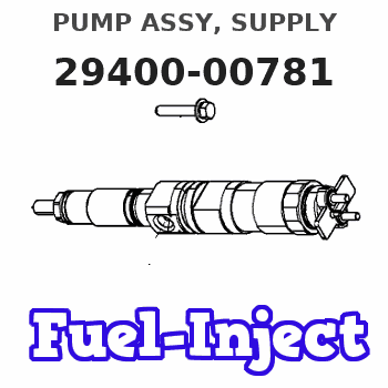
Information pump assy, supply
Rating:
Compare Prices: .
As an associate, we earn commssions on qualifying purchases through the links below

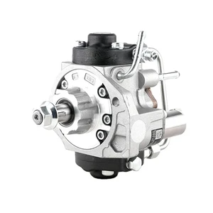
HP3 Fuel Injection Pump for Nissan YD25 D22 D40 2.5L Euro 4 Engine Nissian Navara Pathfinder R51 Pick-Up 294000-0781 16700-VM00D 16700VM00D
KoovDem Part Number: 294000-0781, 16700-VM00A, 16700VM00A, 16700-VM00B, 16700VM00B, 16700-VM00C, 16700VM00C, 16700-VM00D, 16700VM00D || Compatible Model: for Nissan YD25 D22 D40 2.5L Euro 4 Engine; for Nissian Navara 2.5L YD25, DDTi, D22, D40, NP300, dCi, Euro 4; for Nissian Pathfinder 2.5L YD25, D4, DDTi, dCi, Euro 4 || Effective and Reliable: Utilizing cutting-edge technology, this system delivers effective and reliable fuel supply, guaranteeing smooth vehicle performance. || Rugged and Dependable: With a track record of being rigorously tested and proven, this product offers durability and reliability, ensuring it operates consistently even in the harshest of environments. || Straightforward Installation: With a user-friendly interface, installing this product is a breeze. Simply plug it in and you're good to go, no technical expertise needed.
KoovDem Part Number: 294000-0781, 16700-VM00A, 16700VM00A, 16700-VM00B, 16700VM00B, 16700-VM00C, 16700VM00C, 16700-VM00D, 16700VM00D || Compatible Model: for Nissan YD25 D22 D40 2.5L Euro 4 Engine; for Nissian Navara 2.5L YD25, DDTi, D22, D40, NP300, dCi, Euro 4; for Nissian Pathfinder 2.5L YD25, D4, DDTi, dCi, Euro 4 || Effective and Reliable: Utilizing cutting-edge technology, this system delivers effective and reliable fuel supply, guaranteeing smooth vehicle performance. || Rugged and Dependable: With a track record of being rigorously tested and proven, this product offers durability and reliability, ensuring it operates consistently even in the harshest of environments. || Straightforward Installation: With a user-friendly interface, installing this product is a breeze. Simply plug it in and you're good to go, no technical expertise needed.

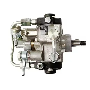
294000-0783 294000-0781 294000-0780 16700-VM00A 16700-VM01C CR HP3 Fuel Injection Pump Suitable for Nissan YD25 2.5L Engine Navara NP300 D40 D22 Pathfinder D4 R51
OfkZynodor Part Name:Fuel Pump || Part Number:294000-0781 294000-0780 || Application:Suitable for Nissan YD25 2.5L Engine Navara NP300 D40 D22 Pathfinder D4 R51 || ◈Please make sure to carefully compare the photos and check the part numbers before making the purchase. If you are unable to confirm your engine model or part number, please leave us a message and we will assist you in confirming that the product you purchase is the one you need. || ◈Your order is not merely a single purchase but the beginning of a cooperative journey, aiming to ensure the safe and smooth operation of your vehicle. We are proud to offer you reliable precision engineering components and unparalleled services.
OfkZynodor Part Name:Fuel Pump || Part Number:294000-0781 294000-0780 || Application:Suitable for Nissan YD25 2.5L Engine Navara NP300 D40 D22 Pathfinder D4 R51 || ◈Please make sure to carefully compare the photos and check the part numbers before making the purchase. If you are unable to confirm your engine model or part number, please leave us a message and we will assist you in confirming that the product you purchase is the one you need. || ◈Your order is not merely a single purchase but the beginning of a cooperative journey, aiming to ensure the safe and smooth operation of your vehicle. We are proud to offer you reliable precision engineering components and unparalleled services.

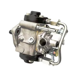
IMIFAFTAbT 294000-0781 294000-0783 16700-VM00A Fuel Injection Pump CR HP3 for Nissan YD25 2.5L Engine for Nissan Navara NP300 D40 D22 Pathfinder D4 R51
IMIFAFTAbT Part Name:Fuel Injection Pump 294000-0781 294000-0783 16700-VM00A || Part Number:294000-0781 294000-0783 16700-VM00A || APPlication: Compatible with Nissan YD25 2.5L Engine for Nissan Navara NP300 D40 D22 Pathfinder D4 R51 || If you are not sure if the product is suitable please leave us a message and send us your original || product picture and part number and we will send the correct part after confirmation
IMIFAFTAbT Part Name:Fuel Injection Pump 294000-0781 294000-0783 16700-VM00A || Part Number:294000-0781 294000-0783 16700-VM00A || APPlication: Compatible with Nissan YD25 2.5L Engine for Nissan Navara NP300 D40 D22 Pathfinder D4 R51 || If you are not sure if the product is suitable please leave us a message and send us your original || product picture and part number and we will send the correct part after confirmation
You can express buy:
USD 406
19-05-2025
19-05-2025
Injection Pump 294000-0780 294000-0781 094000-0783 294000-0785 16700 VM01A 16700-VM01C for NISSAN YD25 Pathfinder/Navara
USD 395.21
19-05-2025
19-05-2025
Injection Pump 294000-0780 294000-0781 094000-0783 294000-0785 16700 VM01A 16700-VM01C for NISSAN YD25 Pathfinder/Navara
USD 399.82
19-05-2025
19-05-2025
16700VM00A diesel Fuel Pump 294000-0780 294000-0781 294000-0782
Images:
USD 391.58

[19-May-2025]
USD 391.86

[19-May-2025]
USD 460.02

[19-May-2025]
USD 393.14

[13-May-2025]
Scheme ###:

| 000. | [01] | 29400-00780 | PUMP ASSY, SUPPLY | 16700VM00A |
| 000. | [01] | 29400-00781 | PUMP ASSY, SUPPLY | 16700VM00D |
| 001. | [01] | 29410-01001 | HOUSING SUB-ASSY, | SM |
| 002. | [02] | 29417-80060 | WASHER, CAMSHAFT | SM |
| 003. | [01] | 29419-10050 | CAMSHAFT, SUPPLY P | SM |
| 003. | [01] | 29419-10080 | CAMSHAFT, SUPPLY P | SM |
| 004. | [01] | 29402-10040 | KEY, WOODRUFF | |
| 004. | [01] | 29402-10020 | KEY, WOODRUFF | |
| 005. | [01] | 29417-00070 | RING SUB-ASSY, CAM | SM |
| 005. | [01] | 29417-00130 | RING SUB-ASSY, CAM | SM |
| 005. | [01] | 29417-00240 | RING SUB-ASSY, CAM | SM |
| 006. | [01] | 29412-00290 | COVER SUB-ASSY, BE | SM |
| 006. | [01] | 29412-00330 | COVER SUB-ASSY, BE | SM |
| 006-001. | [01] | 29419-70010 | SEAL, OIL | |
| 007. | [06] | 09644-90380 | BOLT, SOCKET | SM |
| 008. | [01] | 29419-80120 | O-RING, SUPPLY PUM | SM |
| 009. | [02] | 29419-80100 | O-RING, SUPPLY PUM | SM |
| 010. | [01] | 29418-30141 | PLATE, FEED PUMP, | SM |
| 011. | [01] | 29418-40120 | COVER, FEED PUMP | SM |
| 012. | [01] | 29418-70040 | KEY, FEED PUMP | |
| 012. | [01] | 29418-70010 | KEY, FEED PUMP | |
| 013. | [01] | 29418-00090 | ROTOR SET, FEED PU | SM |
| 014. | [05] | 09644-90370 | BOLT, SOCKET | SM |
| 015. | [01] | 29409-00290 | ELEMENT KIT, SUPPL | SM |
| 015. | [01] | 29409-00560 | ELEMENT KIT, SUPPL | SM |
| 015. | [01] | 29409-01050 | ELEMENT KIT, SUPPL | SM |
| 016. | [01] | 29409-01040 | ELEMENT KIT, SUPPL | SM |
| 016. | [01] | 29409-00530 | ELEMENT KIT, SUPPL | SM |
| 016. | [01] | 29409-00300 | ELEMENT KIT, SUPPL | SM |
| 017. | [02] | 29415-90040 | SPRING, PLUNGER | |
| 018. | [02] | 29419-80080 | O-RING, SUPPLY PUM | SM |
| 019. | [02] | 29419-80110 | O-RING, SUPPLY PUM | SM |
| 020. | [06] | 29419-90030 | BOLT, SOCKET | SM |
| 030. | [01] | 29419-80150 | O-RING, SUPPLY PUM | SM |
| 031. | [01] | 17973-00100 | SENSOR, FUEL TEMPE | |
| 032. | [01] | 29420-00360 | VALVE ASSY, SUCTIO | SM |
| 032. | [01] | 29420-00160 | VALVE ASSY, SUCTIO | SM |
| 032-001. | [01] | 29428-60030 | O-RING, VALVE | SM |
| 033. | [01] | 29428-50030 | O-RING, SOLENOID | SM |
| 034. | [01] | 29416-00071 | VALVE SUB-ASSY, RE | SM |
| 034. | [01] | 29416-00130 | VALVE SUB-ASSY, RE | SM |
| 034. | [01] | 29416-00200 | VALVE SUB-ASSY, RE | SM |
| 034-001. | [01] | 29419-80130 | O-RING, SUPPLY PUM | SM |
| 034-002. | [01] | 29419-80140 | O-RING, SUPPLY PUM | SM |
| 035. | [01] | 29401-00071 | PIPE, SUPPLY PUMP | SM |
| 036. | [02] | 29416-90010 | PIN, STOPPER | |
| 037. | [01] | 29411-50031 | PLUG, FILTER | SM |
| 038. | [01] | 29411-70020 | GASKET, PLUG | SM |
| 039. | [01] | 09737-00050 | FILTER SUB-ASSY | SM |
| 040. | [01] | 29419-80160 | O-RING, SUPPLY PUM | SM |
| 042. | [01] | 29425-90020 | GASKET, SOLENOID | |
| 052. | [01] | 09001-45170 | CAP, VALVE HOLDER | SM |
| 053. | [01] | 09808-10100 | COVER, RUBBER | SM |
| 054. | [01] | 09808-10110 | COVER, RUBBER | SM |
| 101. | [01] | 29400-90010 | OVERHAUL KIT, SUPP | SM |
| 102. | [01] | 29400-90100 | OVERHAUL KIT, SUPP | SM |
| 200. | [01] | 29400-90080 | OVERHAUL KIT, SUPP | SM |
Include in #3:
29400-00781
as PUMP ASSY, SUPPLY
Cross reference number
| Part num | Firm num | Firm | Name |
| 29400-00781 | 16700VM00D | PUMP ASSY, SUPPLY |
Information:
Procedure for Pressure Lubrication
1. Clean the tank of the 1P540 Flow Checking Tool Group thoroughly, and set the pressure regulator to 35 5 psi (240 35 kPa).
Air pressure should not be more than 50 psi (345 kPa) at any time.
2. Put approximately one gallon of engine oil in the tank.
PRESSURE LUBRICATION (Using the 1P540 Flow Checking Tool Group)3. Connect the tooling to the engine as shown. The tap shown is connected to the main oil passage.4. Add air pressure to the tank, with the regulator set at 35 5 psi (240 35 kPa). Although the tank does have a hand pump, it is difficult to get enough air pressure to do the job with the hand pump. Therefore, use of shop air is recommended.5. Let the one gallon of engine oil flow into the oil passage under pressure.When filling the crankcase, put in one gallon of oil less than the recommendation in the Lubrication and Maintenance Guides, if engine has received this pressure lubrication application. Also, if the engine is not going to be used for a long time, do the above procedure again before the first starting.If shop air is not available for charging the tank, the hand pump may be used to get the minimum required pressure.
Do not use the same 1P540 Flow Checking Tool Group for both "pressure lubrication application" and for checking fuel flow. Incorrect cleaning is probable if the tool is used for both fuel and lube oil. Even a minute amount of dirt in the fuel system can cause fuel nozzle failure.
Dynamometer Test Precaution
To avoid possible engine damage while testing on a dynamometer, the thermostats must be installed and the shunt line connected as shown.
SHUNT LINE CONNECTED TO ENGINEInitial Operation After Engine Reconditioning
The quality of oil control components used in Caterpillar engines is such that, following engine reconditioning (with Caterpillar Service Parts), only an initial operational check is necessary before continued operation in normal service.The purpose of this initial operational check is to: insure that the engine has been assembled properly; determine if proper pressures and temperatures are maintained in the lubrication, cooling and fuel systems; correct any leaks; perform necessary adjustments (such as valve clearance, governor high and low idle speeds, etc.); check the power setting of the engine.To provide a safe, uniform initial operational check, the following procedure is recommended: 1. Motor engine at cranking speed until oil pressure is observed.2. Operate engine for 10 minutes at low idle.3. Operate engine for 15 minutes at half-load and 3/4 rated speed.4. Operate engine for 30 minutes at rated load and speed.