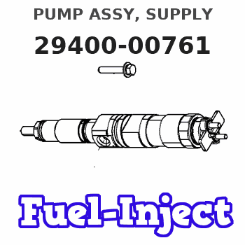
Information pump assy, supply
Rating:
Compare Prices: .
As an associate, we earn commssions on qualifying purchases through the links below

Fuel injection Pump 294000-0760 16625AA010 for Subaru Engine EE20Z
AUCALIWI Part number:294000-0760,16625AA010 || Application:for Subaru Engine EE20Z
AUCALIWI Part number:294000-0760,16625AA010 || Application:for Subaru Engine EE20Z

Fuel injection Pump 294000-0760 16625AA010 for Subaru Engine EE20Z
ADPelcote Part number:294000-0760 || Applications:for Subaru Engine EE20Z
ADPelcote Part number:294000-0760 || Applications:for Subaru Engine EE20Z

$386.43
22 Oct 2024
CN: CAR REFINE
16625AA010 294000-0760 Fuel Injection Pump Type for Subaru Engine EE20Z
Podafu Part Name: Fuel Injection Pump || Part Number: 16625AA010 || Applicable: Compatible with Subaru Engine EE20Z || The fuel injection pump has a long service life, low maintenance frequency, and high reliability || Before purchasing, please carefully check if the product is suitable for your vehicle by reviewing the part number and photos.
Podafu Part Name: Fuel Injection Pump || Part Number: 16625AA010 || Applicable: Compatible with Subaru Engine EE20Z || The fuel injection pump has a long service life, low maintenance frequency, and high reliability || Before purchasing, please carefully check if the product is suitable for your vehicle by reviewing the part number and photos.
Scheme ###:

| 000. | [01] | 29400-00760 | PUMP ASSY, SUPPLY | 16625AA010 |
| 000. | [01] | 29400-00761 | PUMP ASSY, SUPPLY | 16625AA010 |
| 000. | [01] | 29400-00764 | PUMP ASSY, SUPPLY | 16625AA011 |
| 001. | [01] | 29410-00920 | HOUSING SUB-ASSY, | |
| 002. | [02] | 29417-80040 | WASHER, CAMSHAFT | |
| 003. | [01] | 29419-10040 | CAMSHAFT, SUPPLY P | |
| 004. | [01] | 29402-10020 | KEY, WOODRUFF | |
| 005. | [01] | 29417-00220 | RING SUB-ASSY, CAM | |
| 005. | [01] | 29417-00140 | RING SUB-ASSY, CAM | |
| 006. | [01] | 29412-00310 | COVER SUB-ASSY, BE | |
| 006-001. | [01] | 29419-70010 | SEAL, OIL | |
| 007. | [06] | 09644-90110 | BOLT, SOCKET | |
| 008. | [01] | 29419-80050 | O-RING, SUPPLY PUM | |
| 009. | [02] | 29419-80030 | O-RING, SUPPLY PUM | |
| 010. | [01] | 29418-30160 | PLATE, FEED PUMP, | |
| 011. | [01] | 29418-40110 | COVER, FEED PUMP | |
| 012. | [01] | 29418-70030 | KEY, FEED PUMP | |
| 012. | [01] | 29418-70050 | KEY, FEED PUMP | |
| 013. | [01] | 29418-00110 | ROTOR SET, FEED PU | |
| 014. | [05] | 09644-90050 | BOLT, SOCKET | |
| 015. | [01] | 29409-00510 | ELEMENT KIT, SUPPL | |
| 015. | [01] | 29409-00070 | ELEMENT KIT, SUPPL | |
| 015. | [01] | 29409-00410 | ELEMENT KIT, SUPPL | |
| 016. | [01] | 29409-00290 | ELEMENT KIT, SUPPL | |
| 016. | [01] | 29409-00100 | ELEMENT KIT, SUPPL | |
| 016. | [01] | 29409-00940 | ELEMENT KIT, SUPPL | |
| 017. | [02] | 29415-90040 | SPRING, PLUNGER | |
| 018. | [02] | 29419-80010 | O-RING, SUPPLY PUM | |
| 019. | [02] | 29419-80040 | O-RING, SUPPLY PUM | |
| 020. | [06] | 29419-90010 | BOLT, SOCKET | |
| 031. | [01] | 09806-60030 | O-RING, DISTRIBUTI | |
| 032. | [01] | 17973-00100 | SENSOR, FUEL TEMPE | |
| 033. | [01] | 29420-00160 | VALVE ASSY, SUCTIO | |
| 033. | [01] | 29420-00360 | VALVE ASSY, SUCTIO | |
| 033-001. | [01] | 29428-60030 | O-RING, VALVE | |
| 034. | [01] | 29428-50040 | O-RING, SOLENOID | |
| 035. | [01] | 29416-00130 | VALVE SUB-ASSY, RE | |
| 035. | [01] | 29416-00200 | VALVE SUB-ASSY, RE | |
| 035-001. | [01] | 29419-80060 | O-RING, SUPPLY PUM | |
| 035-002. | [01] | 29419-80070 | O-RING, SUPPLY PUM | |
| 036. | [01] | 29401-00100 | PIPE, SUPPLY PUMP | |
| 037. | [02] | 29416-90010 | PIN, STOPPER | |
| 038. | [01] | 29411-50010 | PLUG, FILTER | |
| 039. | [01] | 29411-70010 | GASKET, PLUG | |
| 040. | [01] | 09737-00010 | FILTER SUB-ASSY | |
| 041. | [01] | 09604-90460 | O-RING | |
| 043. | [01] | 29425-90020 | GASKET, SOLENOID | |
| 044. | [01] | 94918-00310 | SCREW, HOLLOW | |
| 045. | [02] | 94901-02490 | WASHER | |
| 046. | [01] | 94919-80270 | COLLAR, PRESSBOARD | |
| 052. | [01] | 09001-40180 | CAP, VALVE HOLDER | |
| 053. | [01] | 94905-62390 | NUT | |
| 054. | [01] | 09646-80060 | CAP RUBBER | |
| 101. | [01] | 29400-90010 | OVERHAUL KIT, SUPP | |
| 102. | [01] | 29400-90100 | OVERHAUL KIT, SUPP | |
| 200. | [01] | 29400-90031 | OVERHAUL KIT, SUPP |
Include in #3:
29400-00761
as PUMP ASSY, SUPPLY
Cross reference number
| Part num | Firm num | Firm | Name |
| 29400-00761 | 16625AA010 | PUMP ASSY, SUPPLY |
Information:
REMOVING CAM FOLLOWERS WITH MAGNET2. Rotate the crankshaft CLOCKWISE (as viewed from front of engine) until the timing mark on crankshaft gear is aligned with timing mark on camshaft large gear.3. Remove the plug from timing pin hole in fuel injection pump housing and install timing pin (1).4. Remove the tachometer drive adapter housing.5. On engines equipped with the hydraulic governor; Remove the automatic timing advance unit or the fuel injection pump camshaft drive gear by removing the tachometer drive shaft with a 9S5031 (5/8 in.) Deep Well Socket. Using puller group (2), thread the 9S8528 Bolt Assembly into the fuel injection pump camshaft. Do not force the bolt assembly. It should thread easily. Install the 9S8527 Bolt by threading it into the automatic timing advance unit or the fuel injection pump camshaft drive gear. Then tighten the 9S8527 Bolt with a wrench until the automatic timing advance unit or fuel injection pump camshaft drive gear "pops" loose.On engines equipped with the "Max-Min" governor; Loosen the automatic timing advance unit retaining bolt with a 8S2357 (9/16in.) Deep Well Socket. The bolt will first feel loose, then it will tighten again when the taper drive of the automatic timing advance unit starts to separate from the camshaft.
TIMING PIN AND PULLER INSTALLED
1. FT887 Timing Pin (Fabricated Tool). 2. 9S8520 Puller Group.6. Remove the camshaft thrust pin (3) from the rear of the cylinder block.
REMOVING THRUST PIN
3. Thrust pin.7. Pull the camshaft (4) out of the cylinder block, being careful to not damage the camshaft bearings or journals.
REMOVING CAMSHAFT
4. Camshaft.Install Camshaft
1. Lubricate the camshaft bearing surfaces with clean engine oil (SAE 30).2. Install the camshaft with timing mark on camshaft gear aligned with timing mark on crankshaft gear.3. Install the camshaft thrust pin in rear of cylinder block. Tighten the thrust pin to 35 5 lb. ft. (4.8 0.7 mkg).4. Position the automatic timing advance unit or fuel injection pump drive gear on the fuel injection pump camshaft. Install the tachometer drive shaft. Engines equipped with the hydraulic governor; Tighten retaining bolt to 32 2 lb. ft. (4.4 0.3 mkg). Engines equipped with the "Max-Min" governor; Tighten retaining bolt to 35 2 lb. ft. (4.8 0.3 mkg).5. Remove timing pin from fuel injection pump housing and install plug in timing pin hole.6. Install the cam followers in the same location from which they were removed. Always use new cam followers with a new camshaft. Be sure to put clean engine oil on the cam followers and camshaft lobes before installing the cam followers.