Information pump assy, supply
Rating:
Compare Prices: .
As an associate, we earn commssions on qualifying purchases through the links below

Compatible with Mitsubishi Engine L3E Fuel Injection Pump 094500-5160 094500-7040 MM436649
KoovDem Part Number:RE533507 RE53 3507 || Part Name: Fuel Injection Pump || The package includes one piece of the Fuel Injection Pump with the product code RE533507 or RE53 3507.
KoovDem Part Number:RE533507 RE53 3507 || Part Name: Fuel Injection Pump || The package includes one piece of the Fuel Injection Pump with the product code RE533507 or RE53 3507.

Fuel Injection Pump 294000-075 RE533507 for John Deere 4045T 6068T S350
ADPelcote Part number:294000-075 || Applications:for John Deere 4045T 6068T S350
ADPelcote Part number:294000-075 || Applications:for John Deere 4045T 6068T S350

Haiyazhma Fuel Injection Pump RE533507 RE53 3507 Compatible with John Deere Engine 4045T 6068T S350
Haiyazhma Part Name: Fuel Injection Pump || Part Number: RE533507 RE53 3507 Note: Please check the fitment carefully before purchase. Or just tell us the part number you need. || Engine Model: 4045T || Applicable: Compatible with John Deere Engine 4045T 6068T S350 || Package included: 1pcs Fuel Injection Pump RE533507 RE53 3507
Haiyazhma Part Name: Fuel Injection Pump || Part Number: RE533507 RE53 3507 Note: Please check the fitment carefully before purchase. Or just tell us the part number you need. || Engine Model: 4045T || Applicable: Compatible with John Deere Engine 4045T 6068T S350 || Package included: 1pcs Fuel Injection Pump RE533507 RE53 3507
Components :
| 001. | PUMP ASSY, SUPPLY | 29400-00750 |
| 001. | PUMP ASSY, SUPPLY | 29400-00750 |
Scheme ###:
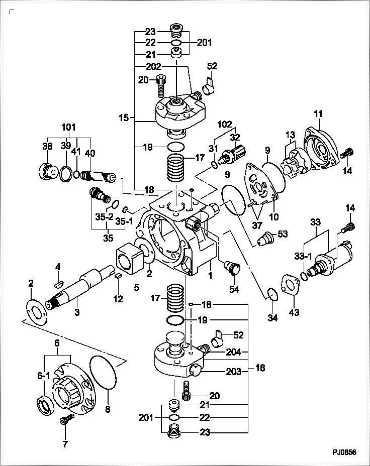
| 000. | [01] | 29400-00750 | PUMP ASSY, SUPPLY | RE533507 |
| 000. | [01] | 29400-00751 | PUMP ASSY, SUPPLY | RE546119 |
| 001. | [01] | 29410-00900 | HOUSING SUB-ASSY, | |
| 002. | [02] | 29417-80040 | WASHER, CAMSHAFT | |
| 003. | [01] | 29419-10010 | CAMSHAFT, SUPPLY P | |
| 003. | [01] | 29419-10080 | CAMSHAFT, SUPPLY P | |
| 004. | [01] | 29402-10040 | KEY, WOODRUFF | |
| 004. | [01] | 29402-10020 | KEY, WOODRUFF | |
| 005. | [01] | 29417-00120 | RING SUB-ASSY, CAM | |
| 005. | [01] | 29417-00210 | RING SUB-ASSY, CAM | |
| 006. | [01] | 29412-00310 | COVER SUB-ASSY, BE | |
| 006-001. | [01] | 29419-70010 | SEAL, OIL | |
| 007. | [06] | 09644-90110 | BOLT, SOCKET | |
| 008. | [01] | 29419-80050 | O-RING, SUPPLY PUM | |
| 009. | [02] | 29419-80030 | O-RING, SUPPLY PUM | |
| 010. | [01] | 29418-30160 | PLATE, FEED PUMP, | |
| 011. | [01] | 29418-40080 | COVER, FEED PUMP | |
| 012. | [01] | 29418-70010 | KEY, FEED PUMP | |
| 012. | [01] | 29418-70040 | KEY, FEED PUMP | |
| 013. | [01] | 29418-00080 | ROTOR SET, FEED PU | |
| 014. | [05] | 09644-90050 | BOLT, SOCKET | |
| 015. | [01] | 29409-00380 | ELEMENT KIT, SUPPL | |
| 015. | [01] | 29409-00690 | ELEMENT KIT, SUPPL | |
| 016. | [01] | 29409-00390 | ELEMENT KIT, SUPPL | |
| 016. | [01] | 29409-00760 | ELEMENT KIT, SUPPL | |
| 017. | [02] | 29415-90040 | SPRING, PLUNGER | |
| 018. | [02] | 29419-80010 | O-RING, SUPPLY PUM | |
| 019. | [02] | 29419-80040 | O-RING, SUPPLY PUM | |
| 020. | [06] | 29419-90010 | BOLT, SOCKET | |
| 031. | [01] | 09806-60030 | O-RING, DISTRIBUTI | |
| 032. | [01] | 17973-00100 | SENSOR, FUEL TEMPE | |
| 033. | [01] | 29420-00360 | VALVE ASSY, SUCTIO | |
| 033-001. | [01] | 29428-60030 | O-RING, VALVE | |
| 034. | [01] | 29428-50040 | O-RING, SOLENOID | |
| 035. | [01] | 29416-00011 | VALVE SUB-ASSY, RE | |
| 035. | [01] | 29416-00200 | VALVE SUB-ASSY, RE | |
| 035-001. | [01] | 29419-80060 | O-RING, SUPPLY PUM | |
| 035-002. | [01] | 29419-80070 | O-RING, SUPPLY PUM | |
| 037. | [02] | 29416-90010 | PIN, STOPPER | |
| 038. | [01] | 29411-50010 | PLUG, FILTER | |
| 039. | [01] | 29411-70010 | GASKET, PLUG | |
| 040. | [01] | 09737-00010 | FILTER SUB-ASSY | |
| 041. | [01] | 09604-90460 | O-RING | |
| 043. | [01] | 29425-90020 | GASKET, SOLENOID | |
| 052. | [02] | 09001-40160 | CAP, VALVE HOLDER | |
| 053. | [01] | 09003-45220 | PLUG | |
| 054. | [01] | 09003-45230 | PLUG | |
| 101. | [01] | 29400-90010 | OVERHAUL KIT, SUPP | RE516999 |
| 102. | [01] | 29400-90100 | OVERHAUL KIT, SUPP | RE516336 |
| 200. | [01] | 29400-90031 | OVERHAUL KIT, SUPP |
Include in #3:
29400-00750
as PUMP ASSY, SUPPLY
Cross reference number
| Part num | Firm num | Firm | Name |
| 29400-00750 | RE533507 | PUMP ASSY, SUPPLY | |
| RE533507 | JOHN DEERE | PUMP ASSY SUPPLY | |
| RE546119 | JOHN DEERE | PUMP ASSY, SUPPLY |
Information:
REMOVING CONNECTING ROD BEARING CAP4. Push the piston and connecting rod upward until the piston rings clear the cylinder block. Remove the piston and connecting rod from the cylinder block.
REMOVING PISTON
Do not allow the connecting rods to hit the bottom edge of the cylinder bores or crankshaft journals when removing or installing. Check the lower portion of the bores for burrs or scratches. Use crocus cloth to remove any burrs or scratches from bottom edge of the bores.
5. Keep the connecting rod bearing cap with its respective connecting rod and piston.6. Repeat Steps 2 through 5 for the remaining pistons.Install Pistons
1. Rotate the crankshaft to position bearing journal of the piston to be installed.2. Lubricate the crankshaft bearing journal, bore in cylinder block, piston, rings, and connecting rod bearings with clean engine oil (SAE 30).3. Install a 1Y7426 Ring Compressor (3), or the 4S9450 Compressor (1) and the 4S9446 Clamp (2) from the 4S9458 Teflon Seal Tool Group, on the piston to compress the rings. Install the piston and connecting rod in cylinder bore with piston crater toward vee of engine. Guide the lower end of connecting rod over the crankshaft journal to prevent damage to the crankshaft.
INSTALLING PISTON
1. 4S9450 Compressor. 2. 4S9446 Clamp.
INSTALLING PISTON ALTERNATE METHOD
3. 1Y7426 Ring Compressor.4. Install the connecting rod cap to connecting rod so numbers correspond and both numbers appear on the same side. Lubricate bolt threads, seating faces of cap and nuts, install the retaining nuts and tighten to 30 3 lb. ft. (4.1 0.4 mkg). Mark cap and nut with matching marks. Tighten additional from mark 60° 5°.5. Repeat Steps 1 thru 4 for the remaining pistons.Disassemble Piston
PISTON ASSEMBLY1. Use ring expander (1) to remove rings.
REMOVING RINGS
1. 5F9059 Ring Expander.2. Remove snap ring (5) and push piston pin (2) out of piston (4) and connecting rod (3).
PISTON DISASSEMBLED
2. Piston pin. 3. Connecting rod. 4. Piston. 5. Snap ring.Assemble Piston
1. Install connecting rod into piston with boss on rod on same side as crater in piston crown.
CONNECTING ROD AND PISTON
CONNECTING ROD AND PISTON Installation of connecting rods WITHOUT BOSS on rod; Install connecting rod into piston with cylinder identification number (as marked on the lower end of the rod and on the cap) 180° opposite the crater in piston crown.2. Install piston pin and snap rings.3. Use the 8S2304 Piston Ring Groove Cleaner to clean the piston ring grooves before installing piston rings.4. Install oil ring spring (6) before installing oil ring.
8S2304 RING GROOVE CLEANER
INSTALLING OIL RING SPRING
6. Oil ring spring.5. Use a 5F9059 Ring Expander to install piston rings. Install compression ring with side marked "TOP" toward top of piston. Install oil ring with gap 180° from oil ring spring joint and approximately 120° from compression ring gap.