Information pump assy, supply

Rating:
Compare Prices: .
As an associate, we earn commssions on qualifying purchases through the links below

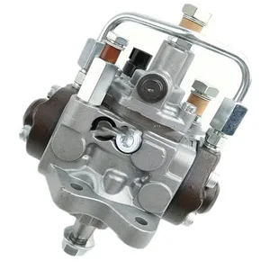
1J574-50503 1J574-50502 294000-0690 Fuel Injection Pump Suitable for Kubota Engine V3800DI Tractor
OfkZynodor Part Name:Fuel Injection Pump || Part Number:1J574-50503 1J574-50502 294000-0690 || Application: Suitable for Kubota Engine V3800DI Tractor || Please make sure to carefully compare the photos and check the part numbers before making the purchase. If you are unable to confirm your engine model or part number, please leave us a message and we will assist you in confirming that the product you purchase is the one you need. || Your order is not merely a single purchase but the beginning of a cooperative journey, aiming to ensure the safe and smooth operation of your vehicle. We are proud to offer you reliable precision engineering components and unparalleled services.
OfkZynodor Part Name:Fuel Injection Pump || Part Number:1J574-50503 1J574-50502 294000-0690 || Application: Suitable for Kubota Engine V3800DI Tractor || Please make sure to carefully compare the photos and check the part numbers before making the purchase. If you are unable to confirm your engine model or part number, please leave us a message and we will assist you in confirming that the product you purchase is the one you need. || Your order is not merely a single purchase but the beginning of a cooperative journey, aiming to ensure the safe and smooth operation of your vehicle. We are proud to offer you reliable precision engineering components and unparalleled services.

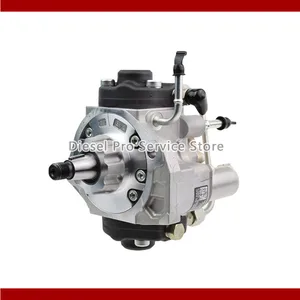
Nayuank Fuel Injection Pump 1J574-50500 1J574-50501 294000-0690 Fits For Kubota Tractor M108D M100XDTC M108DSC Engine V3800DI
Nayuank Part Name: Fuel Injection Pump || Part Number: 1J574-50500 1J574-50501 294000-0690 Note: Please check the fitment carefully before purchase. Or just tell us the part number you need. || Engine Model: V3800DI || Applicable: Fits For Kubota Tractor M108D M100XDTC M108DSC Engine V3800DI || Package included: 1pcs Fuel Injection Pump 1J574-50500 1J574-50501 294000-0690
Nayuank Part Name: Fuel Injection Pump || Part Number: 1J574-50500 1J574-50501 294000-0690 Note: Please check the fitment carefully before purchase. Or just tell us the part number you need. || Engine Model: V3800DI || Applicable: Fits For Kubota Tractor M108D M100XDTC M108DSC Engine V3800DI || Package included: 1pcs Fuel Injection Pump 1J574-50500 1J574-50501 294000-0690

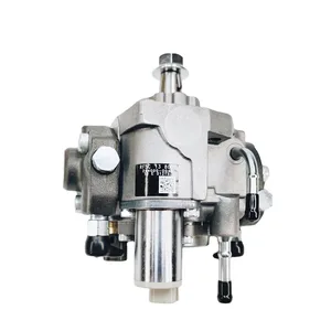
IMELBUFF 1J574-50504 1J57450504 294000-0690 HP3 Fuel Injection Pump for Kubota V3800 V3800DI Engine M108S M108SDSL M108SDS M108SH M108SDSF M108XDTC M100XDTC M110XDTC Tractors
IMELBUFF 🚜Part Number: 1J574-50504, 1J574-50501, 1J574-50503, 294000-0690, 294000-0691, 294000-0692, 294000-0693 || 🚜Engine Model: for Kubota V3800 V3800DI Engine || 🚜Vehicle Application: for Kubota Tractors M108SDSL, M108SDSL2, M108SDSLS, M108SDSL2S, M108SDSCC, M108SH, M108SDSF, M108SHD, M108SDS, M108SDS2, M108XDTC, M100XDTC, M110XDC, M110XDTC || 🚜Warm Tips: If you are not sure that the pump is suitable for your vehicle, please send us email with your vehicle engine model and fuel pump part number || 🚜Service: 6-months-warranty and 24 hour support for customer service. Please feel free to contact us by email if you have any question with the product
IMELBUFF 🚜Part Number: 1J574-50504, 1J574-50501, 1J574-50503, 294000-0690, 294000-0691, 294000-0692, 294000-0693 || 🚜Engine Model: for Kubota V3800 V3800DI Engine || 🚜Vehicle Application: for Kubota Tractors M108SDSL, M108SDSL2, M108SDSLS, M108SDSL2S, M108SDSCC, M108SH, M108SDSF, M108SHD, M108SDS, M108SDS2, M108XDTC, M100XDTC, M110XDC, M110XDTC || 🚜Warm Tips: If you are not sure that the pump is suitable for your vehicle, please send us email with your vehicle engine model and fuel pump part number || 🚜Service: 6-months-warranty and 24 hour support for customer service. Please feel free to contact us by email if you have any question with the product
You can express buy:
USD 399.96
14-06-2025
14-06-2025
Automotive Accessories Parts High Performance Fuel Pump Kit 294000-0690
USD 391.72
14-06-2025
14-06-2025
Automotive Accessories Parts High Performance Fuel Pump Kit 294000-0690
USD 441
13-05-2025
13-05-2025
Automotive Accessories Parts High Performance Fuel Pump Kit 294000-0690
Images:
USD 385.99

[02-May-2025]
Components :
| 001. | PUMP ASSY, SUPPLY | 29400-00690 |
| 001. | PUMP ASSY, SUPPLY | 29400-00690 |
| 001. | PUMP ASSY, SUPPLY | 29400-00690 |
| 002. | OVERHAUL KIT, SUPP | 29400-90031 |
Scheme ###:
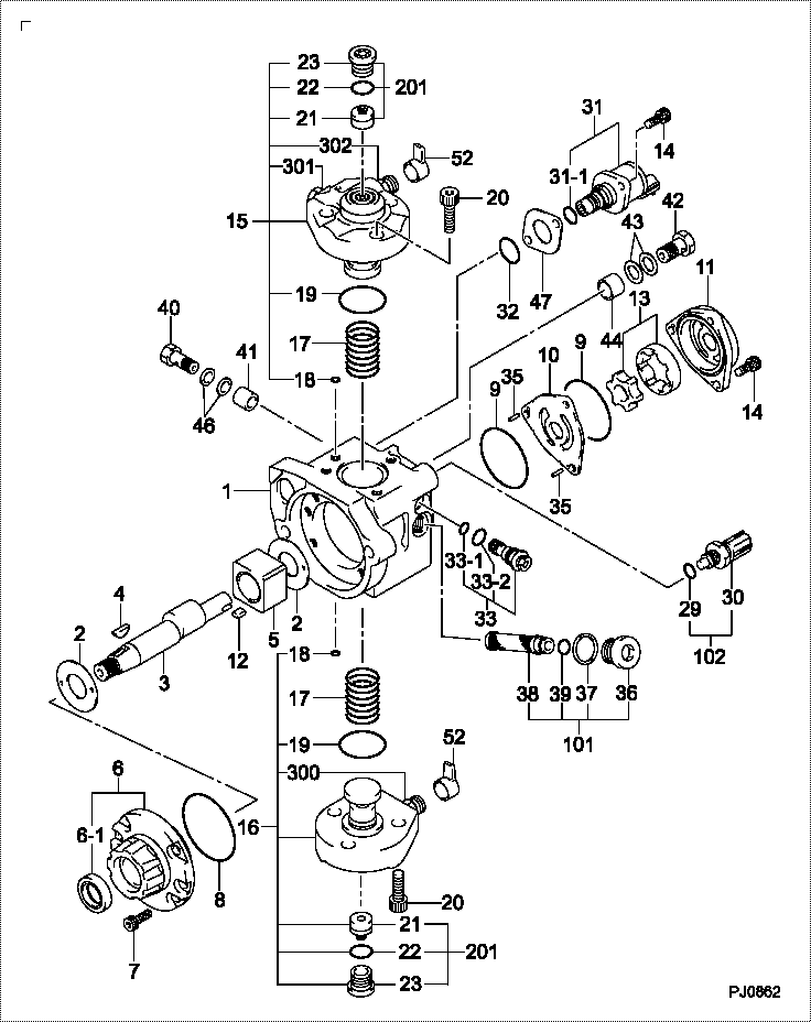
| 000. | [01] | 29400-00690 | PUMP ASSY, SUPPLY | 1J574-50501 |
| 000. | [01] | 29400-00691 | PUMP ASSY, SUPPLY | 1J574-50502 |
| 000. | [01] | 29400-00692 | PUMP ASSY, SUPPLY | 1J574-50503 |
| 001. | [01] | 29410-00850 | HOUSING SUB-ASSY, | |
| 002. | [02] | 29417-80040 | WASHER, CAMSHAFT | |
| 003. | [01] | 29419-10010 | CAMSHAFT, SUPPLY P | |
| 003. | [01] | 29419-10080 | CAMSHAFT, SUPPLY P | |
| 004. | [01] | 29402-10040 | KEY, WOODRUFF | |
| 004. | [01] | 29402-10020 | KEY, WOODRUFF | |
| 005. | [01] | 29417-00120 | RING SUB-ASSY, CAM | |
| 005. | [01] | 29417-00210 | RING SUB-ASSY, CAM | |
| 006. | [01] | 29412-00310 | COVER SUB-ASSY, BE | |
| 006-001. | [01] | 29419-70010 | SEAL, OIL | |
| 007. | [06] | 09644-90110 | BOLT, SOCKET | |
| 008. | [01] | 29419-80050 | O-RING, SUPPLY PUM | |
| 009. | [02] | 29419-80030 | O-RING, SUPPLY PUM | |
| 010. | [01] | 29418-30170 | PLATE, FEED PUMP, | |
| 011. | [01] | 29418-40140 | COVER, FEED PUMP | |
| 012. | [01] | 29418-70010 | KEY, FEED PUMP | |
| 012. | [01] | 29418-70040 | KEY, FEED PUMP | |
| 013. | [01] | 29418-00080 | ROTOR SET, FEED PU | |
| 014. | [05] | 09644-90050 | BOLT, SOCKET | |
| 015. | [01] | 29409-00160 | ELEMENT KIT, SUPPL | |
| 015. | [01] | 29409-00770 | ELEMENT KIT, SUPPL | |
| 016. | [01] | 29409-00640 | ELEMENT KIT, SUPPL | |
| 016. | [01] | 29409-00300 | ELEMENT KIT, SUPPL | |
| 017. | [02] | 29415-90040 | SPRING, PLUNGER | |
| 018. | [02] | 29419-80010 | O-RING, SUPPLY PUM | |
| 019. | [02] | 29419-80040 | O-RING, SUPPLY PUM | |
| 020. | [06] | 29419-90010 | BOLT, SOCKET | |
| 021. | [02] | 29414-00082 | VALVE SUB-ASSY, SU | |
| 021. | [02] | 29414-00150 | VALVE SUB-ASSY, SU | |
| 022. | [02] | 29419-80020 | O-RING, SUPPLY PUM | |
| 023. | [02] | 29413-50010 | PLUG, CYLINDER | |
| 029. | [01] | 09806-60030 | O-RING, DISTRIBUTI | |
| 030. | [01] | 17973-00100 | SENSOR, FUEL TEMPE | |
| 031. | [01] | 29420-00160 | VALVE ASSY, SUCTIO | |
| 031. | [01] | 29420-00360 | VALVE ASSY, SUCTIO | |
| 031-001. | [01] | 29428-60030 | O-RING, VALVE | |
| 032. | [01] | 29428-50040 | O-RING, SOLENOID | |
| 033. | [01] | 29416-00011 | VALVE SUB-ASSY, RE | |
| 033. | [01] | 29416-00200 | VALVE SUB-ASSY, RE | |
| 033-001. | [01] | 29419-80060 | O-RING, SUPPLY PUM | |
| 033-002. | [01] | 29419-80070 | O-RING, SUPPLY PUM | |
| 035. | [02] | 29416-90010 | PIN, STOPPER | |
| 036. | [01] | 29411-50010 | PLUG, FILTER | |
| 037. | [01] | 29411-70010 | GASKET, PLUG | |
| 038. | [01] | 09737-00010 | FILTER SUB-ASSY | |
| 039. | [01] | 09604-90460 | O-RING | |
| 040. | [01] | 94918-00060 | SCREW, HOLLOW | 15101-51721 |
| 041. | [01] | 94919-80260 | COLLAR, PRESSBOARD | |
| 042. | [01] | 94918-00310 | SCREW, HOLLOW | 15101-51321 |
| 043. | [02] | 94901-02490 | WASHER | |
| 044. | [01] | 94919-80270 | COLLAR, PRESSBOARD | |
| 046. | [02] | 94901-02470 | WASHER | |
| 047. | [01] | 29425-90020 | GASKET, SOLENOID | |
| 052. | [02] | 09001-40180 | CAP, VALVE HOLDER | |
| 101. | [01] | 29400-90010 | OVERHAUL KIT, SUPP | |
| 102. | [01] | 29400-90100 | OVERHAUL KIT, SUPP | |
| 200. | [01] | 29400-90031 | OVERHAUL KIT, SUPP | |
| 201. | [02] | 29400-90370 | OVERHAUL KIT, SUPP | |
| 201. | [02] | 29400-90940 | OVERHAUL KIT, SUPP | |
| 300. | [01] | 29409-05010 | ELEMENT KIT, SUPPL | |
| 300. | [01] | 29409-05060 | ELEMENT KIT, SUPPL | |
| 301. | [01] | 29409-05020 | ELEMENT KIT, SUPPL | |
| 301. | [01] | 29409-05070 | ELEMENT KIT, SUPPL | |
| 302. | [01] | 29413-10220 | HOLDER, DELIVERY V |
Include in #3:
29400-00690
as PUMP ASSY, SUPPLY
Cross reference number
| Part num | Firm num | Firm | Name |
| 29400-00690 | 1J574-5050 | PUMP ASSY, SUPPLY | |
| 1J574-50503 | KUBOTA | PUMP ASSY, SUPPLY | |
| 1J574-50502 | KUBOTA | PUMP ASSY, SUPPLY | |
| 1J574-50501 | KUBOTA | PUMP ASSY SUPPLY |
Information:
TIMING GEAR COVER1 Loosen bolt (2). Use two 3/8" NC forcing screws to remove pulley hub (1).2 At installation, tighten bolt to 230 20 lb. ft. (31,8 2,8 m.kg), tap bolt head with a hammer, and again tighten bolt to 230 20 lb. ft. (31,8 2,8 m. kg).3 Heat a new bushing in 250°F. (121°C.) oil for two hours before installation.4 Shim between trunnion hub and support halves to obtain a fit of .002 in. (0,05 mm) loose-to-.003 in. (0,07 mm) tight.5 Trim gasket flush with bottom face of cylinder block. Gaskets will leak if not cut square and flush with oil pan face.Timing Gears
Refer to SERVICE GUIDE for Preliminary Information.8S5132 Puller Plate,8S5133 Expansion Plug,8S6470 Pressure Screw,8B7561 Step Plate,Two 3/8" NF bolts.
Do not rotate the crankshaft with camshaft gear removed.
1 Use an 8S5132 Puller Plate, 8S5133 Expansion Plug, 8B7561 Step Plate, two 3/8" NF bolts and an 8S6470 Pressure Screw to remove gear. At installation, refer to topic FUEL INJECTION PUMP CAMSHAFT TIMING - FUEL SYSTEM - TESTING AND ADJUSTING.2 Fuel transfer pump must be removed before removing shaft. At installation, accessory drive shaft must be timed to crankshaft. Refer to FUEL INJECTION PUMP CAMSHAFT TIMING - FUEL SYSTEM - TESTING AND ADJUSTING.3 Trim gasket flush with bottom face of cylinder block. Gasket will leak if not cut square and flush with oil pan face.4, 6 Bearing must be centered in gear hub.5 Install washer with concave side toward gear (1).7 Align letter "C" on camshaft gear with letter "C" on crankshaft gear.8 Camshaft front bearing must be recessed .06 in. (1,52 mm) from front face of bore, oil hole in bearing must align with oil hole in cylinder block, and joint in bearing must face cylinder block centerline. Intermediate bearings must be flush with front face of bearing bore. Rear bearing must be recessed .06 in. (1,52 mm) from rear face of bore.Flywheel And Flywheel Housing
Refer to SERVICE GUIDE for Preliminary Information.FT125 Pilot and FT638 Sleeve (Fabricated Tools),5H1504 Washer,2J3506 Nut. 1, 2 Align mark on flywheel with mark on crankshaft.3 Heat ring gear. Do not exceed 600°F. (315°C.). Install with chamfered portion of ring gear teeth toward starter pinion when flywheel is installed.4 Use FT125 Pilot, FT638 Sleeve, 5H1504 Washer and a 2J3506 Nut to install seal.5 Trim gasket flush with bottom face of cylinder block. Gasket will leak if not cut square and flush with oil pan face.
This is an example of installing the crankshaft rear seal. A-FT638 Sleeve. B-2J3506 Nut. C-5H1504 Washer. D-FT125 Pilot. Secure pilot to crankshaft with three 5/8"-18 NF bolts, 2 in. (50,8 mm) long. Grind bolt head as necessary to provide seal clearance.