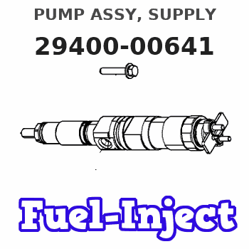
Information pump assy, supply
Rating:
Compare Prices: .
As an associate, we earn commssions on qualifying purchases through the links below

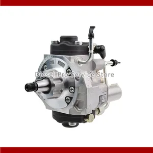
Diesel Fuel Injector Pump Injection Pump Compatible With MITSUBISHI L200 TRITON 4D56 Motor 294000-0640 294000-0641 1460A019
HNUSLIPZ Easy installation: automotive fuel injection pump design is reasonable, the installation method is simple and clear || Injection pressure: The engine fuel pump can produce a higher injection pressure, so that the fuel is better atomized, improve the engine power output || Stable operation: The fuel injection pump can maintain stable fuel injection pressure under high load and harsh working conditions, and has a long service life || Reduced fuel consumption: Fuel supply pumps reduce fuel waste and reduce vehicle operating costs by optimizing fuel injection control || Diesel Fuel Injector Pump Injection Pump Compatible With MITSUBISHI L200 TRITON 4D56 Motor 294000-0640 294000-0641 1460A019
HNUSLIPZ Easy installation: automotive fuel injection pump design is reasonable, the installation method is simple and clear || Injection pressure: The engine fuel pump can produce a higher injection pressure, so that the fuel is better atomized, improve the engine power output || Stable operation: The fuel injection pump can maintain stable fuel injection pressure under high load and harsh working conditions, and has a long service life || Reduced fuel consumption: Fuel supply pumps reduce fuel waste and reduce vehicle operating costs by optimizing fuel injection control || Diesel Fuel Injector Pump Injection Pump Compatible With MITSUBISHI L200 TRITON 4D56 Motor 294000-0640 294000-0641 1460A019

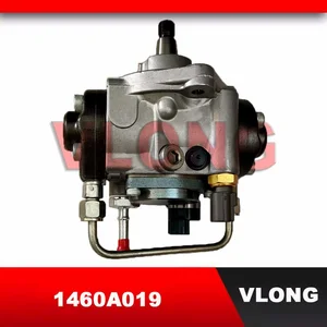
Diesel Common Rail Fuel Pump 294000-0640, Compatible With MITSUBISHI 4D56 Engine, Industrial High-Pressure Replacement, Fits 294000-0641, 294000-1372(294000-0641)
Adfghjk Accurate for 4D56: Pump 294000-0640 addresses P0087/P0251 codes with pressures of 1,800Bar ±1.5%. || Works with High Sulfur Fuels: Nitrided steel plunger tested to ISO 9227 for 2.5 times the life under high sulfur conditions. || Intelligent Pressure Control: Piezo sensor maintains ≤0.5% fluctuation. || HARSH WEATHER CERTIFIED: IP67 and 2,500hr salt spray resistance for use in the tropics. || Quick Installation: Includes seals (MD614344) and can be replaced in less than 2 hours.
Adfghjk Accurate for 4D56: Pump 294000-0640 addresses P0087/P0251 codes with pressures of 1,800Bar ±1.5%. || Works with High Sulfur Fuels: Nitrided steel plunger tested to ISO 9227 for 2.5 times the life under high sulfur conditions. || Intelligent Pressure Control: Piezo sensor maintains ≤0.5% fluctuation. || HARSH WEATHER CERTIFIED: IP67 and 2,500hr salt spray resistance for use in the tropics. || Quick Installation: Includes seals (MD614344) and can be replaced in less than 2 hours.

Diesel Common Rail Fuel Pump 294000-0640, Compatible With MITSUBISHI 4D56 Engine, Industrial High-Pressure Replacement, Fits 294000-0641/1460A019(294000-0641)
Adfghjk Accurate for 4D56: Pump 294000-0640 addresses P0087/P0251 codes with pressures of 1,800Bar ±1.5%. || Works with High Sulfur Fuels: Nitrided steel plunger tested to ISO 9227 for 2.5 times the life under high sulfur conditions. || Intelligent Pressure Control: Piezo sensor maintains ≤0.5% fluctuation. || HARSH WEATHER CERTIFIED: IP67 and 2,500hr salt spray resistance for use in the tropics. || Quick Installation: Includes seals (MD614344) and can be replaced in less than 2 hours.
Adfghjk Accurate for 4D56: Pump 294000-0640 addresses P0087/P0251 codes with pressures of 1,800Bar ±1.5%. || Works with High Sulfur Fuels: Nitrided steel plunger tested to ISO 9227 for 2.5 times the life under high sulfur conditions. || Intelligent Pressure Control: Piezo sensor maintains ≤0.5% fluctuation. || HARSH WEATHER CERTIFIED: IP67 and 2,500hr salt spray resistance for use in the tropics. || Quick Installation: Includes seals (MD614344) and can be replaced in less than 2 hours.
You can express buy:
USD 392.84
29-05-2025
29-05-2025
New fuel pump 294000-1372 1460A053 294000-1242 294000-0641 294000-1240 1460A057
USD 560.5
19-05-2025
19-05-2025
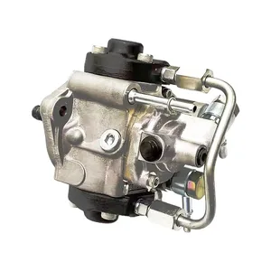
High Pressure Fuel Injection Pump HP3 Diesel Oil Pump Assembly 1460A019 294000-0641 Common Rail Pump For MITSUBISHI L200 4D56
USD 398.84
19-05-2025
19-05-2025
New fuel pump 294000-1372 1460A053 294000-1242 294000-0641 294000-1240 1460A057
Images:
USD 498

[13-May-2025]
USD 391.15

[19-May-2025]
USD 568.54

[19-May-2025]
USD 628.72

[19-May-2025]
Components :
| 001. | PUMP ASSY, SUPPLY | 29400-00641 |
| 002. | OVERHAUL KIT, SUPP | 29400-90080 |
Scheme ###:

| 000. | [01] | 29400-00641 | PUMP ASSY, SUPPLY | 1460A019 |
| 001. | [01] | 29410-00560 | HOUSING SUB-ASSY, | SM |
| 002. | [02] | 29417-80060 | WASHER, CAMSHAFT | SM |
| 003. | [01] | 29419-10060 | CAMSHAFT, SUPPLY P | SM |
| 004. | [01] | 29402-10020 | KEY, WOODRUFF | |
| 005. | [01] | 29417-00260 | RING SUB-ASSY, CAM | SM |
| 005. | [01] | 29417-00150 | RING SUB-ASSY, CAM | SM |
| 006. | [01] | 29412-00250 | COVER SUB-ASSY, BE | SM |
| 006. | [01] | 29412-00330 | COVER SUB-ASSY, BE | SM |
| 006-001. | [01] | 29419-70010 | SEAL, OIL | |
| 007. | [06] | 09644-90380 | BOLT, SOCKET | SM |
| 008. | [01] | 29419-80120 | O-RING, SUPPLY PUM | SM |
| 009. | [02] | 29419-80100 | O-RING, SUPPLY PUM | SM |
| 010. | [01] | 29418-30141 | PLATE, FEED PUMP, | SM |
| 011. | [01] | 29418-40130 | COVER, FEED PUMP | SM |
| 012. | [01] | 29418-70030 | KEY, FEED PUMP | |
| 012. | [01] | 29418-70050 | KEY, FEED PUMP | |
| 013. | [01] | 29418-00100 | ROTOR SET, FEED PU | SM |
| 014. | [05] | 09644-90370 | BOLT, SOCKET | SM |
| 015. | [01] | 29409-00750 | ELEMENT KIT, SUPPL | SM |
| 015. | [01] | 29409-00540 | ELEMENT KIT, SUPPL | SM |
| 015. | [01] | 29409-00150 | ELEMENT KIT, SUPPL | SM |
| 016. | [01] | 29409-00160 | ELEMENT KIT, SUPPL | SM |
| 016. | [01] | 29409-00550 | ELEMENT KIT, SUPPL | SM |
| 016. | [01] | 29409-00770 | ELEMENT KIT, SUPPL | SM |
| 017. | [02] | 29415-90040 | SPRING, PLUNGER | |
| 018. | [02] | 29419-80080 | O-RING, SUPPLY PUM | SM |
| 019. | [02] | 29419-80110 | O-RING, SUPPLY PUM | SM |
| 020. | [06] | 29419-90030 | BOLT, SOCKET | SM |
| 031. | [01] | 29419-80150 | O-RING, SUPPLY PUM | SM |
| 032. | [01] | 17973-00100 | SENSOR, FUEL TEMPE | |
| 033. | [01] | 29420-00160 | VALVE ASSY, SUCTIO | SM |
| 033. | [01] | 29420-00360 | VALVE ASSY, SUCTIO | SM |
| 033-001. | [01] | 29428-60030 | O-RING, VALVE | SM |
| 034. | [01] | 29428-50030 | O-RING, SOLENOID | SM |
| 035. | [01] | 29416-00120 | VALVE SUB-ASSY, RE | SM |
| 035. | [01] | 29416-00160 | VALVE SUB-ASSY, RE | SM |
| 035. | [01] | 29416-00210 | VALVE SUB-ASSY, RE | SM |
| 035-001. | [01] | 29419-80130 | O-RING, SUPPLY PUM | SM |
| 035-002. | [01] | 29419-80140 | O-RING, SUPPLY PUM | SM |
| 036. | [01] | 29401-00071 | PIPE, SUPPLY PUMP | SM |
| 037. | [02] | 29416-90010 | PIN, STOPPER | |
| 038. | [01] | 29411-50031 | PLUG, FILTER | SM |
| 039. | [01] | 29411-70020 | GASKET, PLUG | SM |
| 040. | [01] | 09737-00050 | FILTER SUB-ASSY | SM |
| 041. | [01] | 29419-80160 | O-RING, SUPPLY PUM | SM |
| 043. | [01] | 29425-90020 | GASKET, SOLENOID | |
| 052. | [01] | 09001-45170 | CAP, VALVE HOLDER | SM |
| 053. | [01] | 09808-10100 | COVER, RUBBER | SM |
| 054. | [01] | 09808-10110 | COVER, RUBBER | SM |
| 101. | [01] | 29400-90010 | OVERHAUL KIT, SUPP | SM |
| 102. | [01] | 29400-90100 | OVERHAUL KIT, SUPP | SM |
| 200. | [01] | 29400-90080 | OVERHAUL KIT, SUPP | SM |
Include in #3:
29400-00641
as PUMP ASSY, SUPPLY
Cross reference number
| Part num | Firm num | Firm | Name |
| 29400-00641 | 1460A019 | PUMP ASSY, SUPPLY |
Information:
Fuel system components identified are: 1-Fuel injection nozzles. 2-Fuel lines. 3-Fuel priming pump. 4-Governor. 5-Fuel injection pump housing. 6-Fuel filter. 7-Fuel transfer pump. 8-Tachometer drive.Governor
Removal and Installation
Refer to SERVICE GUIDE for Preliminary Information.
1-Cover. 2-Plate. 3-Cover assembly.
4-Collar. 5-Housing assembly.
6-Spring. 7-Weight assembly.Governor Disassembly and Assembly
1 Guide must be damaged to be removed. When installing a new guide, form the end of the guide against and all the way around the chamfer in the governor housing.2 When assembling weights to carrier, stake four places around each dowel on both ends. Each weight must have .001-.007 in. (0,03-0,18 mm) end play and pivot freely on its dowel.Fuel Transfer Pump
Refer to SERVICE GUIDE for Preliminary Information.8S6747 Sealing Compound 1,3 Apply a thin film of 8S6747 Sealing Compound to mating surfaces when assembling. Do not allow compound to enter pump.2 Use suitable puller and step plate to remove gear. Refer to GENERAL INSTRUCTIONS. Lubricate gear teeth with multipurpose grease before assembling pump to engine.Tachometer Drive
Fuel Pump Housing
Refer to SERVICE GUIDE for Preliminary Information. 8S2315 Wrench8S2244 Extractor.1, 2, 5 Inspect seals.3 Tighten nozzle finger tight on body.4 Use 8S2315 Wrench to remove.6 Use 8S2244 Extractor to remove and install fuel pumps. When installing, sight down the pump and align the notches in the bonnet and barrel with the mark 180° from the pump gear segment center tooth. Position the pump so the notches align with the guide pins in the housing bore. Align the pump gear segment center tooth with the fuel rack center notch. Install the pump. Keep a downward force on the pump and install bushing (4) until flush with the top of the housing. If the bushing can not be assembled this far by hand, remove it. Realign the components and install again.7 When removing retaining ring, do not damage or lose the check valve or spring retained in the bonnet.8, 9 Use extreme care when inserting plunger into barrel. Barrels and plungers are matched and are not interchangeable.10 Fuel rack must be removed before removing lifters and installed after installing lifters.10, 11 Install each spacer and lifter assembly in the same location from which they were removed. Keep them together and identified as to location.12, 13 Remove bearings (12) and (13) with a suitable driver. When installing, position bearing (12) with oil passages aligned vertically (that is, one at the top and one at the bottom). Install bearing (12) .195" .005" deep from the housing face.14, 15, 16 Use commercially available camshaft bearing removal tools. Align oil hole in bearing (14) with the oil passage in the housing.Fuel Ratio Control
Fuel Priming Pump