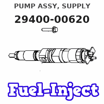
Information pump assy, supply
Rating:
Compare Prices: .
As an associate, we earn commssions on qualifying purchases through the links below

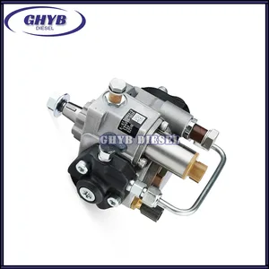
Aftermarket Fuel injection Pump 294000-0620 R2AA13800 Fit Intended For Engine R2AA
Generic Motorcycle Parts || Heavy Equipment Parts || Spare Parts || Fuel Systems
Generic Motorcycle Parts || Heavy Equipment Parts || Spare Parts || Fuel Systems

YRGGHUI Common Rail Diesel Fuel Injection Pump 294000-0620 R2AA13800,Compatible for Mazda
YRGGHUI OEM NO. : 294000-0620 R2AA13800 || Types of automotive components: fuel pump, diesel pump, high-pressure fuel pump components, fuel pump components || Fuel pump: can enhance power, reduce fuel consumption, provide strong power, accelerate smoothly, and ensure the stability of the fuel pump at high temperatures. Make your car full of power || Before purchasing a fuel pump, please confirm if the picture and OEM number match your part! This is really important! If they are not the same component, they cannot be used! All products undergo testing before shipment!! || If you have any questions, please feel free to contact us and we will reply within 24 hours. Please confirm the product based on your vehicle model, year, code, and tag number. thank you. Automotive parts have accurate OEM numbers. Please ensure that the OEM number is suitable for your car
YRGGHUI OEM NO. : 294000-0620 R2AA13800 || Types of automotive components: fuel pump, diesel pump, high-pressure fuel pump components, fuel pump components || Fuel pump: can enhance power, reduce fuel consumption, provide strong power, accelerate smoothly, and ensure the stability of the fuel pump at high temperatures. Make your car full of power || Before purchasing a fuel pump, please confirm if the picture and OEM number match your part! This is really important! If they are not the same component, they cannot be used! All products undergo testing before shipment!! || If you have any questions, please feel free to contact us and we will reply within 24 hours. Please confirm the product based on your vehicle model, year, code, and tag number. thank you. Automotive parts have accurate OEM numbers. Please ensure that the OEM number is suitable for your car

Compatible with Mazda Diesel Engine R2AA Fuel Injection Pump 294000-0620 R2AA13800
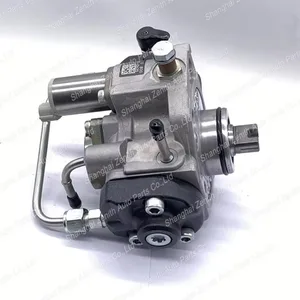
KoovDem Part Number: 294000-0620 R2AA13800 Note: Please check the fitment carefully before purchase. Or just tell us the part number you need. || Part Name: Fuel Injection Pump || The compact and powerful R2AA engine is designed for various vehicles, offering a balance between performance and environmental friendliness. Its efficient fuel consumption and low emissions make it ideal for sedans and small trucks. Known for reliability and durability, it is a popular choice for drivers seeking a dependable powertrain. Suitable for everyday commuting or off-road adventures, the versatile R2AA engine delivers excellent performance in any situation. || Suitable for use with Mazda Diesel Engine R2AA, this product is designed to work efficiently and effectively in conjunction with the specific requirements of the engine. It is compatible with the necessary components and specifications, ensuring smooth operation and optimal performance. Ideal for vehicles equipped with the Mazda Diesel Engine R2AA, this product is reliable, durable, and designed to deliver consistent results. || Included in the package is one piece of the Fuel Injection Pump with the part number 294000-0620 R2AA13800.
KoovDem Part Number: 294000-0620 R2AA13800 Note: Please check the fitment carefully before purchase. Or just tell us the part number you need. || Part Name: Fuel Injection Pump || The compact and powerful R2AA engine is designed for various vehicles, offering a balance between performance and environmental friendliness. Its efficient fuel consumption and low emissions make it ideal for sedans and small trucks. Known for reliability and durability, it is a popular choice for drivers seeking a dependable powertrain. Suitable for everyday commuting or off-road adventures, the versatile R2AA engine delivers excellent performance in any situation. || Suitable for use with Mazda Diesel Engine R2AA, this product is designed to work efficiently and effectively in conjunction with the specific requirements of the engine. It is compatible with the necessary components and specifications, ensuring smooth operation and optimal performance. Ideal for vehicles equipped with the Mazda Diesel Engine R2AA, this product is reliable, durable, and designed to deliver consistent results. || Included in the package is one piece of the Fuel Injection Pump with the part number 294000-0620 R2AA13800.
You can express buy:
USD 383.35
15-05-2025
15-05-2025
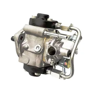
Good Quality Common Rail Diesel Fuel Injection Pump 294000-0620 R2AA13800 For MAZDA
USD 393.4
19-05-2025
19-05-2025
Good Quality Common Rail Diesel Fuel Injection Pump 294000-0620 R2AA13800 For MAZDA
USD 613.29
19-05-2025
19-05-2025
· Fuel Injector pump 294000-0620 for 2940000620 R2AA13800
Images:
USD 876

[13-Oct-2022]
Components :
| 001. | PUMP ASSY, SUPPLY | 29400-00620 |
| 002. | OVERHAUL KIT, SUPP | 29400-90031 |
Scheme ###:
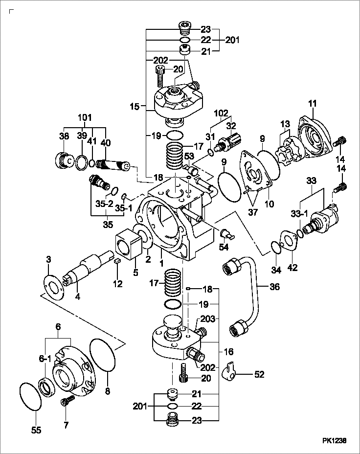
| 000. | [01] | 29400-00620 | PUMP ASSY, SUPPLY | R2AA 13 800 |
| 001. | [01] | 29410-01000 | HOUSING SUB-ASSY, | |
| 002. | [01] | 29417-80040 | WASHER, CAMSHAFT | |
| 003. | [01] | 29417-80080 | WASHER, CAMSHAFT | |
| 004. | [01] | 29419-10070 | CAMSHAFT, SUPPLY P | |
| 005. | [01] | 29417-00210 | RING SUB-ASSY, CAM | |
| 005. | [01] | 29417-00120 | RING SUB-ASSY, CAM | |
| 005. | [01] | 29417-00160 | RING SUB-ASSY, CAM | |
| 006. | [01] | 29412-00350 | COVER SUB-ASSY, BE | |
| 006. | [01] | 29412-00440 | COVER SUB-ASSY, BE | |
| 006-001. | [01] | 29419-70020 | SEAL, OIL | |
| 007. | [06] | 09644-90110 | BOLT, SOCKET | S5A1 13 TD4 |
| 008. | [01] | 29419-80050 | O-RING, SUPPLY PUM | |
| 009. | [02] | 29419-80030 | O-RING, SUPPLY PUM | |
| 010. | [01] | 29418-30160 | PLATE, FEED PUMP, | |
| 011. | [01] | 29418-40080 | COVER, FEED PUMP | |
| 012. | [01] | 29418-70010 | KEY, FEED PUMP | |
| 012. | [01] | 29418-70040 | KEY, FEED PUMP | |
| 013. | [01] | 29418-00080 | ROTOR SET, FEED PU | |
| 014. | [05] | 09644-90050 | BOLT, SOCKET | RF4F 13 V52 |
| 015. | [01] | 29409-00640 | ELEMENT KIT, SUPPL | |
| 015. | [01] | 29409-00780 | ELEMENT KIT, SUPPL | |
| 015. | [01] | 29409-00300 | ELEMENT KIT, SUPPL | |
| 016. | [01] | 29409-00290 | ELEMENT KIT, SUPPL | |
| 016. | [01] | 29409-00790 | ELEMENT KIT, SUPPL | |
| 016. | [01] | 29409-00940 | ELEMENT KIT, SUPPL | |
| 017. | [02] | 29415-90040 | SPRING, PLUNGER | |
| 018. | [02] | 29419-80010 | O-RING, SUPPLY PUM | |
| 019. | [02] | 29419-80040 | O-RING, SUPPLY PUM | |
| 020. | [06] | 29419-90010 | BOLT, SOCKET | |
| 031. | [01] | 09806-60030 | O-RING, DISTRIBUTI | TF88 13 TS2 |
| 032. | [01] | 17973-00100 | SENSOR, FUEL TEMPE | |
| 033. | [01] | 29420-00360 | VALVE ASSY, SUCTIO | |
| 033. | [01] | 29420-00460 | VALVE ASSY, SUCTIO | |
| 033-001. | [01] | 29428-60030 | O-RING, VALVE | |
| 034. | [01] | 29428-50040 | O-RING, SOLENOID | |
| 035. | [01] | 29416-00120 | VALVE SUB-ASSY, RE | |
| 035. | [01] | 29416-00160 | VALVE SUB-ASSY, RE | |
| 035. | [01] | 29416-00210 | VALVE SUB-ASSY, RE | |
| 035-001. | [01] | 29419-80060 | O-RING, SUPPLY PUM | |
| 035-002. | [01] | 29419-80070 | O-RING, SUPPLY PUM | |
| 036. | [01] | 29401-00180 | PIPE, SUPPLY PUMP | |
| 037. | [02] | 29416-90010 | PIN, STOPPER | |
| 038. | [01] | 29411-50010 | PLUG, FILTER | |
| 039. | [01] | 29411-70010 | GASKET, PLUG | |
| 040. | [01] | 09737-00010 | FILTER SUB-ASSY | |
| 041. | [01] | 09604-90460 | O-RING | |
| 042. | [01] | 29425-90020 | GASKET, SOLENOID | |
| 052. | [01] | 09001-40180 | CAP, VALVE HOLDER | |
| 053. | [01] | 09808-10020 | COVER, RUBBER | |
| 054. | [01] | 09646-80060 | CAP RUBBER | |
| 055. | [01] | 29419-80260 | O-RING, SUPPLY PUM | |
| 101. | [01] | 29400-90010 | OVERHAUL KIT, SUPP | |
| 102. | [01] | 29400-90100 | OVERHAUL KIT, SUPP | |
| 200. | [01] | 29400-90031 | OVERHAUL KIT, SUPP |
Include in #3:
29400-00620
as PUMP ASSY, SUPPLY
Cross reference number
| Part num | Firm num | Firm | Name |
| 29400-00620 | R2AA 13 80 | PUMP ASSY, SUPPLY | |
| R213800 | MAZDA | PUMP ASSY SUPPLY | |
| R2AA 13 800 | MAZDA | PUMP ASSY, SUPPLY |
Information:
start by: a) remove vibration damper and pulley 1. Use tooling (A) to remove the crankshaft front seal from the timing gear cover. When a replacement of the front seal is made, a replacement of the wear sleeve is to be made also. 2. Put tool (B) in position in the seal bore as shown.3. Install tool (C) between tool (B) and the wear sleeve. Turn tool (C) until the edge of the tool makes a flat place (crease) in the wear sleeve. Do this in two or more places until the wear sleeve is loose.4. Remove tool (B) and the wear sleeve by hand.5. Clean and make a preparation of the wear sleeve inside diameter and crankshaft outside diameter with 8M8060 Quick Cure Primer. Put 9S3265 Retaining Compound on the crankshaft outside diameter and wear sleeve inside diameter before the wear sleeve is installed on the crankshaft. 6. Put a small amount of clean oil on the lip of the seal. Install wear sleeve (2) and seal (1) on the crankshaft as shown with tools (D). If tools are not available, install the wear sleeve until it is .060 .020 in. (1.52 0.51 mm) (dimension "X") from the face of the crankshaft. Install the seal in the timing gear cover until the metal face of the seal is .090 .020 in. (2.29 0.51 mm) (dimension "Y") from the face of the crankshaft.end by: a) install vibration damper and pulleyRemove And Install Crankshaft Rear Seal And Wear Sleeve
start by:a) remove flywheel 1. Use tool (A) to remove crankshaft rear seal (1) from the flywheel housing. When a replacement of the rear seal is made, a replacement of the wear sleeve is to be made also.
TYPICAL EXAMPLE2. Put tool (B) in position in the seal bore as shown.3. Install tool (C) between tool (B) and the wear sleeve. Turn tool (C) until the edge of the tool makes a flat place (crease) in the wear sleeve. Do this in two or more places until the wear sleeve is loose.4. Remove tool (B) and the wear sleeve by hand.5. Clean and make a preparation of the wear sleeve inside diameter and adapter outside diameter with 8M8060 Quick Cure Primer. Put 9S3265 Retaining Compound on the adapter outside diameter and wear sleeve inside diameter before the wear sleeve is installed on the adapter. Make sure the lip of the seal is toward the inside of the engine and the outside diameter bevel of the wear sleeve is toward the outside of the engine.6. Put a small amount of clean engine oil on the lip of the seal. Install the wear sleeve and the seal on the crankshaft as shown with tools (D).end by:a) install flywheel