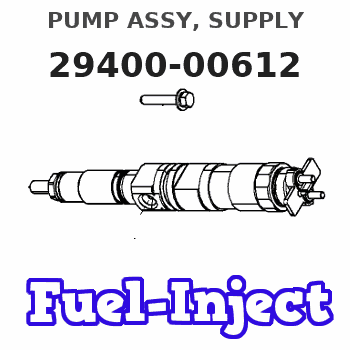
Information pump assy, supply
Rating:
Compare Prices: .
As an associate, we earn commssions on qualifying purchases through the links below

22100-E0031 294000-0612 Fuel Injection Pump Common Rail Pump Fits for Hino 500 Series J05E Engine 5.2L
GENERIC Part Number: 294000-0612 22100-E0031 || Engine Model: for Hino 500 Series J05E Engine || Application: for Kobelco Excavator SK200-8 SK210-8 SK260-8
GENERIC Part Number: 294000-0612 22100-E0031 || Engine Model: for Hino 500 Series J05E Engine || Application: for Kobelco Excavator SK200-8 SK210-8 SK260-8
22100-E0031 294000-0612 Fuel Injection Pump Common Rail Pump Fits for Hino 500 Series J05E Engine 5.2L
ABCGTDLPAS Part Number: 294000-0612 22100-E0031 || Engine Model: for Hino 500 Series J05E Engine || Application: for Kobelco Excavator SK200-8 SK210-8 SK260-8
ABCGTDLPAS Part Number: 294000-0612 22100-E0031 || Engine Model: for Hino 500 Series J05E Engine || Application: for Kobelco Excavator SK200-8 SK210-8 SK260-8
Scheme ###:

| 000. | [01] | 29400-00611 | PUMP ASSY, SUPPLY | 22100-E0030 |
| 000. | [01] | 29400-00616 | PUMP ASSY, SUPPLY | 22100-E0035 |
| 000. | [01] | 29400-00615 | PUMP ASSY, SUPPLY | 22100-E0034 |
| 000. | [01] | 29400-00614 | PUMP ASSY, SUPPLY | 22100-E0033 |
| 000. | [01] | 29400-00613 | PUMP ASSY, SUPPLY | 22100-E0032 |
| 000. | [01] | 29400-00612 | PUMP ASSY, SUPPLY | 22100-E0031 |
| 001. | [01] | 29410-00720 | HOUSING SUB-ASSY, | |
| 001. | [01] | 29410-01290 | HOUSING SUB-ASSY, | |
| 002. | [02] | 29417-80040 | WASHER, CAMSHAFT | |
| 003. | [01] | 29419-10080 | CAMSHAFT, SUPPLY P | |
| 003. | [01] | 29419-10010 | CAMSHAFT, SUPPLY P | |
| 004. | [01] | 29402-10020 | KEY, WOODRUFF | |
| 004. | [01] | 29402-10040 | KEY, WOODRUFF | |
| 005. | [01] | 29417-00120 | RING SUB-ASSY, CAM | |
| 006. | [01] | 29412-00310 | COVER SUB-ASSY, BE | |
| 006-001. | [01] | 29419-70010 | SEAL, OIL | |
| 007. | [06] | 09644-90110 | BOLT, SOCKET | |
| 008. | [01] | 29419-80050 | O-RING, SUPPLY PUM | |
| 009. | [02] | 29419-80030 | O-RING, SUPPLY PUM | |
| 010. | [01] | 29418-30160 | PLATE, FEED PUMP, | |
| 011. | [01] | 29418-40080 | COVER, FEED PUMP | |
| 011. | [01] | 29418-40210 | COVER, FEED PUMP | |
| 012. | [01] | 29418-70010 | KEY, FEED PUMP | |
| 012. | [01] | 29418-70040 | KEY, FEED PUMP | |
| 013. | [01] | 29418-00080 | ROTOR SET, FEED PU | |
| 014. | [05] | 09644-90050 | BOLT, SOCKET | |
| 015. | [01] | 29409-00370 | ELEMENT KIT, SUPPL | |
| 015. | [01] | 29409-00650 | ELEMENT KIT, SUPPL | |
| 016. | [01] | 29409-00640 | ELEMENT KIT, SUPPL | |
| 016. | [01] | 29409-00300 | ELEMENT KIT, SUPPL | |
| 017. | [02] | 29415-90040 | SPRING, PLUNGER | |
| 018. | [02] | 29419-80010 | O-RING, SUPPLY PUM | |
| 019. | [02] | 29419-80040 | O-RING, SUPPLY PUM | |
| 020. | [06] | 29419-90010 | BOLT, SOCKET | |
| 021. | [02] | 29414-00082 | VALVE SUB-ASSY, SU | |
| 021. | [02] | 29414-00150 | VALVE SUB-ASSY, SU | |
| 022. | [02] | 29419-80020 | O-RING, SUPPLY PUM | |
| 023. | [02] | 29413-50010 | PLUG, CYLINDER | |
| 031. | [01] | 09806-60030 | O-RING, DISTRIBUTI | |
| 032. | [01] | 17973-00100 | SENSOR, FUEL TEMPE | |
| 033. | [01] | 29420-00170 | VALVE ASSY, SUCTIO | |
| 033. | [01] | 29420-00370 | VALVE ASSY, SUCTIO | |
| 033. | [01] | 29420-00650 | VALVE ASSY, SUCTIO | |
| 033. | [01] | 29420-03650 | VALVE ASSY, SUCTIO | |
| 033-001. | [01] | 29428-60030 | O-RING, VALVE | |
| 033-001. | [01] | 29428-60010 | O-RING, VALVE | |
| 034. | [01] | 29428-50010 | O-RING, SOLENOID | |
| 034. | [01] | 29428-50040 | O-RING, SOLENOID | |
| 035. | [01] | 29416-00130 | VALVE SUB-ASSY, RE | |
| 035. | [01] | 29416-00200 | VALVE SUB-ASSY, RE | |
| 035-001. | [01] | 29419-80060 | O-RING, SUPPLY PUM | |
| 035-002. | [01] | 29419-80070 | O-RING, SUPPLY PUM | |
| 036. | [01] | 29401-00110 | PIPE, SUPPLY PUMP | |
| 037. | [02] | 29416-90010 | PIN, STOPPER | |
| 038. | [01] | 29411-50010 | PLUG, FILTER | |
| 039. | [01] | 29411-70010 | GASKET, PLUG | |
| 040. | [01] | 09737-00010 | FILTER SUB-ASSY | |
| 041. | [01] | 09604-90460 | O-RING | |
| 042. | [01] | 29425-90020 | GASKET, SOLENOID | |
| 045. | [01] | 94918-00060 | SCREW, HOLLOW | S2283-51110-A |
| 046. | [01] | 94919-80260 | COLLAR, PRESSBOARD | S2233-21650-A |
| 047. | [01] | 94918-00310 | SCREW, HOLLOW | S2283-51310-A |
| 048. | [02] | 94901-02490 | WASHER | S2287-71100-A |
| 049. | [01] | 94919-80270 | COLLAR, PRESSBOARD | S2284-32240-A |
| 052. | [01] | 09001-40160 | CAP, VALVE HOLDER | |
| 053. | [01] | 94905-62390 | NUT | S2282-52570-A |
| 101. | [01] | 29400-90010 | OVERHAUL KIT, SUPP | |
| 102. | [01] | 29400-90100 | OVERHAUL KIT, SUPP | |
| 200. | [01] | 29400-90031 | OVERHAUL KIT, SUPP | |
| 201. | [02] | 29400-90370 | OVERHAUL KIT, SUPP | |
| 201. | [02] | 29400-90940 | OVERHAUL KIT, SUPP | |
| 202. | [01] | 29400-90630 | OVERHAUL KIT, SUPP | |
| 300. | [01] | 29409-05050 | ELEMENT KIT, SUPPL | |
| 301. | [01] | 29409-05060 | ELEMENT KIT, SUPPL | |
| 302. | [01] | 29413-10220 | HOLDER, DELIVERY V |
Include in #3:
29400-00612
as PUMP ASSY, SUPPLY
Cross reference number
| Part num | Firm num | Firm | Name |
| 29400-00612 | 22100-E003 | PUMP ASSY, SUPPLY |
Information:
1. Remove two bolts that hold oil cooler bonnet (3) to the water pump.2. Remove two bolts (1) and remove elbow (2) from the water pump. Remove the gasket and O-ring seal from the elbow. 3. Remove the bolts that hold cover (4) to the water pump. Remove cover (4) from the water pump. It is not necessary to remove bolts (7). The bolts hold the cover to the timing gear cover only.4. Remove six long bolts (5) that hold the water pump to the timing cover. Remove water pump (6)Install Water Pump
1. Check the O-ring seals and gaskets and make replacements if needed. 2. Make sure O-ring seal (1) is in position on the water pump. Put water pump (2) into position in the timing gear cover. Install the bolts that hold the water pump in place. 3. Make sure the O-ring seal is in position and install cover (3) on the water pump. 4. Install the O-ring seal and gasket for elbow (4). Install elbow (4) in the water pump. Install the two bolts that hold the elbow to the water temperature regulator housing.5. Make sure the gasket is in place and install the two bolts that hold oil cooler bonnet (5) to the water pump.Disassemble Water Pump
start by:a) remove water pump 1. Remove O-ring seal (1) from the adapter.2. Remove adapter (2) from the housing. Remove the O-ring seal from the outside diameter of the adapter.3. Remove bolt (3) and retainer that hold the impeller on the shaft. 4. Use tooling (A) to remove impeller (4) from the shaft. 5. Remove spring and seal (5) from the shaft. 6. Remove four bolts (7) from retainer (6) that holds the shaft assembly to the pump housing.7. Remove O-ring seal (8) from the housing. 8. Remove gear and shaft assembly (10) from the housing.9. Remove bolt (9) and retainer from the shaft assembly. 10. Use a press to remove the shaft assembly from gear (11). Remove the retainer from the shaft assembly. 11. Remove bearing (13), spacer (14) and bearing (12) from the shaft. 12. Remove lip type seal (15) from the housing.13. Turn the housing over and remove ceramic ring (16) and the seal.Assemble Water Pump
1. Install bearing (4), spacer (3) and bearing (2) on shaft (8).2. Put retainer (1) and gear (7) in position on the shaft assembly. Install retainer (6) and bolt (5). 3. Use tooling (A) to install the lip seal in the housing. Put a small amount of SAE 30 oil on the lip of the seal. 4. Install a new O-ring seal (10) on the housing.5. Put shaft assembly (9) in position in the housing. Install the bolts that hold the retainer to the housing.
Clean water only is permitted for use as a lubricant for assistanc at installation. Do not damage or put hands on the wear surface of the carbon ring or the ceramic ring. Install the ceramic ring with the smoothest face of the ring toward the carbon seal