Information pump assy, supply

Rating:
Compare Prices: .
As an associate, we earn commssions on qualifying purchases through the links below

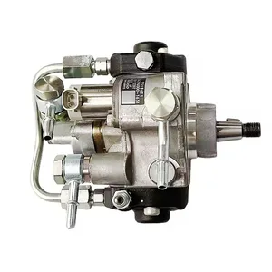
INJECTION Fuel Pump 294000-0580 8-97386558-0 294000-0581 8-97386558-1
TWXLLDRM This fuel injection pump uses cutting-edge injection technology to realize ultra-fine atomization of fuel, greatly improving combustion efficiency, enabling the engine to release more powerful power and significantly improving response speed. || We insist on using aviation-grade high-strength materials, which have excellent high temperature resistance, high pressure resistance and wear resistance. From raw materials to many fine processes on the production line, every step exceeds the quality standards. || Our fuel injection pump provides accurate adaptation models, and in-depth research and development and testing are carried out for the matched models to ensure that the products can perfectly fit your car in terms of interfaces, dimensions, operating parameters and so on. || This fuel injection pump can accurately control the fuel injection quantity, whether on urban roads or at high speed, it can ensure that the engine can get accurate and appropriate fuel, effectively improve fuel utilization and reduce fuel consumption. || INJECTION Fuel Pump 294000-0580 8-97386558-0 294000-0581 8-97386558-1
TWXLLDRM This fuel injection pump uses cutting-edge injection technology to realize ultra-fine atomization of fuel, greatly improving combustion efficiency, enabling the engine to release more powerful power and significantly improving response speed. || We insist on using aviation-grade high-strength materials, which have excellent high temperature resistance, high pressure resistance and wear resistance. From raw materials to many fine processes on the production line, every step exceeds the quality standards. || Our fuel injection pump provides accurate adaptation models, and in-depth research and development and testing are carried out for the matched models to ensure that the products can perfectly fit your car in terms of interfaces, dimensions, operating parameters and so on. || This fuel injection pump can accurately control the fuel injection quantity, whether on urban roads or at high speed, it can ensure that the engine can get accurate and appropriate fuel, effectively improve fuel utilization and reduce fuel consumption. || INJECTION Fuel Pump 294000-0580 8-97386558-0 294000-0581 8-97386558-1

Fuel Injection Pump 294000-0580 8-97386558-0 294000-0581 For Isuzu Diesel Engine 4HK1
oiasdfhjdg Product name:Fuel Injection Pump || Part Number:294000-0580 8-97386558-0 294000-0581 || APPlication:For Isuzu Diesel Engine 4HK1 || 1.Please carefully compare the OE numbers before purchasing the product to match your original parts and avoid wasting your valuable time. || 2.Please ensure to provide us with the correct, accurate, and detailed delivery address and contact information
oiasdfhjdg Product name:Fuel Injection Pump || Part Number:294000-0580 8-97386558-0 294000-0581 || APPlication:For Isuzu Diesel Engine 4HK1 || 1.Please carefully compare the OE numbers before purchasing the product to match your original parts and avoid wasting your valuable time. || 2.Please ensure to provide us with the correct, accurate, and detailed delivery address and contact information

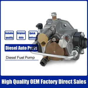
IMIFAFTAbT 294000-0580 8-97386558-0 294000-0581 8-97386558-1 Fuel Injection Pump HP3 Fits For Isuzu 4HK1 5.2L Engine NPR NRR NHR NQR N-Series Truck
IMIFAFTAbT Part Name:Fuel Injection Pump 294000-0580 8-97386558-0 294000-0581 8-97386558-1 || Part Number:294000-0580 8-97386558-0 294000-0581 8-97386558-1 || APPlication: Compatible For Isuzu 4HK1 5.2L Engine N-Series Truck || If you are not sure if the product is suitable please leave us a message and send us your original || product picture and part number and we will send the correct part after confirmation
IMIFAFTAbT Part Name:Fuel Injection Pump 294000-0580 8-97386558-0 294000-0581 8-97386558-1 || Part Number:294000-0580 8-97386558-0 294000-0581 8-97386558-1 || APPlication: Compatible For Isuzu 4HK1 5.2L Engine N-Series Truck || If you are not sure if the product is suitable please leave us a message and send us your original || product picture and part number and we will send the correct part after confirmation
You can express buy:
USD 396.33
19-05-2025
19-05-2025
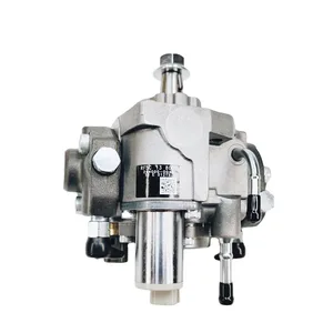
High quality INJECTION Fuel pump 294000-0580 8-97386558-0 294000-0581 8-97386558-1
USD 367.6
17-05-2025
17-05-2025
High quality INJECTION Fuel pump 294000-0580 8-97386558-0 294000-0581 8-97386558-1
USD 441
13-05-2025
13-05-2025
High quality INJECTION Fuel pump 294000-0580 8-97386558-0 294000-0581 8-97386558-1
Images:
USD 694.22

[13-May-2025]
USD 391.72

[19-May-2025]
USD 398.1

[13-May-2025]
USD 385.71

[19-May-2025]
Scheme ###:

| 000. | [01] | 29400-00580 | PUMP ASSY, SUPPLY | 8-97386558-0 |
| 000. | [01] | 29400-00581 | PUMP ASSY, SUPPLY | 8-97386558-1 |
| 001. | [01] | 29410-00780 | HOUSING SUB-ASSY, | |
| 002. | [02] | 29417-80040 | WASHER, CAMSHAFT | |
| 003. | [01] | 29419-10010 | CAMSHAFT, SUPPLY P | |
| 004. | [01] | 29402-10020 | KEY, WOODRUFF | |
| 005. | [01] | 29417-00120 | RING SUB-ASSY, CAM | |
| 006. | [01] | 29412-00310 | COVER SUB-ASSY, BE | |
| 006-001. | [01] | 29419-70010 | SEAL, OIL | |
| 007. | [06] | 29419-90050 | BOLT, SOCKET | |
| 008. | [01] | 29419-80050 | O-RING, SUPPLY PUM | |
| 009. | [02] | 29419-80030 | O-RING, SUPPLY PUM | |
| 010. | [01] | 29418-30170 | PLATE, FEED PUMP, | |
| 011. | [01] | 29418-40140 | COVER, FEED PUMP | |
| 012. | [01] | 29418-70010 | KEY, FEED PUMP | |
| 012. | [01] | 29418-70040 | KEY, FEED PUMP | |
| 013. | [01] | 29418-00080 | ROTOR SET, FEED PU | |
| 014. | [05] | 29419-90040 | BOLT, SOCKET | |
| 015. | [01] | 29409-00370 | ELEMENT KIT, SUPPL | |
| 016. | [01] | 29409-00300 | ELEMENT KIT, SUPPL | |
| 017. | [02] | 29415-90040 | SPRING, PLUNGER | |
| 018. | [02] | 29419-80010 | O-RING, SUPPLY PUM | |
| 019. | [02] | 29419-80040 | O-RING, SUPPLY PUM | |
| 020. | [06] | 29419-90060 | BOLT, SOCKET | |
| 031. | [01] | 09806-60030 | O-RING, DISTRIBUTI | |
| 032. | [01] | 17973-00100 | SENSOR, FUEL TEMPE | |
| 033. | [01] | 29420-00360 | VALVE ASSY, SUCTIO | |
| 033. | [01] | 29420-00160 | VALVE ASSY, SUCTIO | |
| 033. | [01] | 29420-00210 | VALVE ASSY, SUCTIO | |
| 033-001. | [01] | 29428-60030 | O-RING, VALVE | |
| 034. | [01] | 29428-50040 | O-RING, SOLENOID | |
| 035. | [01] | 29416-00011 | VALVE SUB-ASSY, RE | |
| 035. | [01] | 29416-00130 | VALVE SUB-ASSY, RE | |
| 035-001. | [01] | 29419-80060 | O-RING, SUPPLY PUM | |
| 035-002. | [01] | 29419-80070 | O-RING, SUPPLY PUM | |
| 036. | [01] | 29401-00120 | PIPE, SUPPLY PUMP | |
| 036. | [01] | 29401-00200 | PIPE, SUPPLY PUMP | |
| 037. | [02] | 29416-90010 | PIN, STOPPER | |
| 038. | [01] | 29411-50040 | PLUG, FILTER | |
| 039. | [01] | 29411-70010 | GASKET, PLUG | |
| 040. | [01] | 09737-00010 | FILTER SUB-ASSY | |
| 041. | [01] | 09604-90460 | O-RING | |
| 042. | [01] | 29425-90020 | GASKET, SOLENOID | |
| 044. | [01] | 09543-80010 | SCREW, HOLLOW | |
| 044. | [01] | 09543-80170 | SCREW, HOLLOW | 8-97351388-0 |
| 045. | [02] | 94901-02530 | WASHER | 8-97602218-0 |
| 046. | [01] | 94919-80260 | COLLAR, PRESSBOARD | |
| 047. | [01] | 94918-00310 | SCREW, HOLLOW | 5-15759003-0 |
| 048. | [02] | 94901-02490 | WASHER | 1-15619507-0 |
| 049. | [01] | 94919-80270 | COLLAR, PRESSBOARD | |
| 052. | [01] | 09001-40160 | CAP, VALVE HOLDER | |
| 101. | [01] | 29400-90010 | OVERHAUL KIT, SUPP | |
| 102. | [01] | 29400-90100 | OVERHAUL KIT, SUPP | |
| 200. | [01] | 29400-90031 | OVERHAUL KIT, SUPP |
Include in #3:
29400-00581
as PUMP ASSY, SUPPLY
Cross reference number
| Part num | Firm num | Firm | Name |
| 29400-00581 | 8-97386558 | PUMP ASSY, SUPPLY |
Information:
1. Remove bolt (1) from the alternator and bracket. 2. Remove the two bolts that hold bracket (3) to the timing gear cover.3. Disconnect water line (2) from the air compressor. 4. Remove bolts (4) and (5) that hold the cylinder head to the cylinder block. 5. Fasten a hoist and remove cylinder head (6). The weight is approximately 300 lb. (135 kg).
Do not put the cylinder head down on a flat surface. This can cause damage to the fuel injection valves.
6. Remove the seals from the spacer plate.Install Cylinder Head Assembly
Be sure a new gasket has been installed between the spacer plate and the cylinder block. See REMOVE AND INSTALL SPACER PLATE. 1. Thoroughly clean the spacer plate and the bottom surface of the cylinder head. Install a new head gasket and new seals (1). Later model engines have two O-ring seals on top and bottom of the spacer plate. 2. Fasten a hoist and put cylinder head (2) in position on the cylinder block. 3. Put clean engine oil on the threads of the cylinder head bolts. Install the cylinder head bolts and washers. Tighten the bolts in sequence shown in illustration A87019x1: a) Tighten bolts 1 through 20 in number sequence to a torque of 200 20 lb.ft. (270 25 N m).b) Tighten bolts 1 through 20 in number sequence to a torque of 330 15 lb.ft. (450 20 N m).c) Tighten bolts 1 through 20 in number sequence to a torque of 330 15 lb.ft. (450 20 N m) by hand.d) Install rocker shafts and push rods. See INSTALL ROCKER SHAFTS AND PUSH RODS.e) Tighten bolts 21 through 26 in number sequence to a torque of 200 20 lb.ft. (270 25 N m).f) Tighten bolts 21 through 26 in number sequence to a torque of 330 15 lb.ft. (450 20 N m).g) Tighten bolts 21 through 26 in number sequence to a torque of 330 15 lb.ft. (450 20 N m) by hand.h) Tighten the 3/8" bolts to a torque of 32 5 lb. ft. (43 7 N m). If the studs for the exhaust manifold were removed, install new studs and tighten to 20 3 lb.ft. (25 4 N m).4. Make a adjustment to the valves to have a clearance of .015 (0.38 mm) for intake and .030 (0.76 mm) for exhaust. Install the valve cover bases and the inner fuel lines. Tighten the locknuts for the valve adjustment screws to a torque of 22 3 lb.ft. (28 4 N m).5. Install the valve cover bases and the inner fuel lines. See INSTALL ROCKER SHAFT AND PUSH RODS.6. Install the valve covers. See INSTALL VALVE COVERS. 7. Connect water line (3) to the air compressor. 8. Install bolt (4) for the alternator.end by:a) install exhaust manifoldb) install fuel injection linesc) install inlet manifoldd) install water temperature regulator