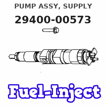
Information pump assy, supply
Rating:
Compare Prices: .
As an associate, we earn commssions on qualifying purchases through the links below

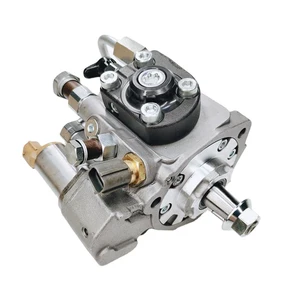
YRGGHUI HP3 Diesel Fuel Injection Pump Assembly 294000-0573 8-97386557-3,Compatible for Isuzu 4HK1
YRGGHUI OEM NO.:294000-0573 8-97386557-3 || Types of automotive components: fuel pump, diesel pump, high-pressure fuel pump components, fuel pump components || Fuel pump: can enhance power, reduce fuel consumption, provide strong power, accelerate smoothly, and ensure the stability of the fuel pump at high temperatures. Make your car full of power || Before purchasing a fuel pump, please confirm if the picture and OEM number match your part! This is really important! If they are not the same component, they cannot be used! All products undergo testing before shipment!! || If you have any questions, please feel free to contact us and we will reply within 24 hours. Please confirm the product based on your vehicle model, year, code, and tag number. thank you. Automotive parts have accurate OEM numbers. Please ensure that the OEM number is suitable for your car
YRGGHUI OEM NO.:294000-0573 8-97386557-3 || Types of automotive components: fuel pump, diesel pump, high-pressure fuel pump components, fuel pump components || Fuel pump: can enhance power, reduce fuel consumption, provide strong power, accelerate smoothly, and ensure the stability of the fuel pump at high temperatures. Make your car full of power || Before purchasing a fuel pump, please confirm if the picture and OEM number match your part! This is really important! If they are not the same component, they cannot be used! All products undergo testing before shipment!! || If you have any questions, please feel free to contact us and we will reply within 24 hours. Please confirm the product based on your vehicle model, year, code, and tag number. thank you. Automotive parts have accurate OEM numbers. Please ensure that the OEM number is suitable for your car

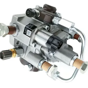
8-97386557-3 CR HP3 Fuel Injection Pump Compatible with Isuzu 5.2L 4HK1 4HK1-TCC 4HK1-TCS Diesel Engine F-Series Medium Duty Trucks 294000-0573 294000-0572
KoovDem Part Number: 294000-0573 294000-0572 8-97386557-3 2940000573 2940000572 8973865573 || Vehicle Application:For Isuzu FRR FSR FTR FVR FSS F-Series Medium Duty Trucks || The engine model is designed for Isuzu vehicles with a displacement of 5.2 liters. It is specifically designed for the 4HK1, 4HK1-TCC, and 4HK1-TCS engines. || for verification. This will help ensure that you receive the correct part for your vehicle. It is important to double check the accuracy of the part numbers to avoid any delays or inconvenience. Thank you for your attention to detail and for choosing our services. || Service: We offer a 5-month warranty on all products, along with 24-hour customer support for any inquiries or issues. If you have any questions regarding the product, please don't hesitate to reach out to us via email.
KoovDem Part Number: 294000-0573 294000-0572 8-97386557-3 2940000573 2940000572 8973865573 || Vehicle Application:For Isuzu FRR FSR FTR FVR FSS F-Series Medium Duty Trucks || The engine model is designed for Isuzu vehicles with a displacement of 5.2 liters. It is specifically designed for the 4HK1, 4HK1-TCC, and 4HK1-TCS engines. || for verification. This will help ensure that you receive the correct part for your vehicle. It is important to double check the accuracy of the part numbers to avoid any delays or inconvenience. Thank you for your attention to detail and for choosing our services. || Service: We offer a 5-month warranty on all products, along with 24-hour customer support for any inquiries or issues. If you have any questions regarding the product, please don't hesitate to reach out to us via email.

HP3 Diesel Fuel Injection Pump Assembly 294000-0573 8-97386557-3,Compatible For ISUZU 4HK1
DYVWMRKX Using high-quality materials and precision manufacturing processes. || The jet pump is designed to provide stable and sufficient fuel flow. || HP3 Diesel Fuel Injection Pump Assembly 294000-0573 8-97386557-3 || Jet pumps have a long service life and good durability, reducing the frequency of malfunctions and repairs. || The fuel pump ensures that the engine can obtain the required fuel under various operating conditions, improving engine performance.
DYVWMRKX Using high-quality materials and precision manufacturing processes. || The jet pump is designed to provide stable and sufficient fuel flow. || HP3 Diesel Fuel Injection Pump Assembly 294000-0573 8-97386557-3 || Jet pumps have a long service life and good durability, reducing the frequency of malfunctions and repairs. || The fuel pump ensures that the engine can obtain the required fuel under various operating conditions, improving engine performance.
You can express buy:
USD 393.14
13-05-2025
13-05-2025
Diesel Common Rail Fuel Pump 294000-0573 8-97386557-3 8973865573 For ISUZU 4HK1
USD 423.29
19-05-2025
19-05-2025
HP3 Diesel Fuel Injection Pump Assembly 294000-0573 8-97386557-3 for ISUZU 4HK1
USD 396.61
19-05-2025
19-05-2025
Diesel fuel pump engine fuel pump 294000-0574 8-97386557-1 294000-0571 294000-0572 8-97386557-2 294000-0573
Images:
USD 401.22

[19-May-2025]
USD 890.45

[19-May-2025]
USD 401.22

[19-May-2025]
USD 384.18

[19-May-2025]
Scheme ###:

| 000. | [01] | 29400-00571 | PUMP ASSY, SUPPLY | 8-97386557-1 |
| 000. | [01] | 29400-00572 | PUMP ASSY, SUPPLY | 8-97386557-2 |
| 000. | [01] | 29400-00573 | PUMP ASSY, SUPPLY | 8-97386557-3 |
| 001. | [01] | 29410-00680 | HOUSING SUB-ASSY, | |
| 002. | [02] | 29417-80040 | WASHER, CAMSHAFT | |
| 003. | [01] | 29419-10010 | CAMSHAFT, SUPPLY P | |
| 004. | [01] | 29402-10020 | KEY, WOODRUFF | |
| 005. | [01] | 29417-00120 | RING SUB-ASSY, CAM | |
| 005. | [01] | 29417-00010 | RING SUB-ASSY, CAM | |
| 006. | [01] | 29412-00270 | COVER SUB-ASSY, BE | |
| 006. | [01] | 29412-00310 | COVER SUB-ASSY, BE | |
| 006-001. | [01] | 29419-70010 | SEAL, OIL | |
| 007. | [06] | 29419-90050 | BOLT, SOCKET | |
| 008. | [01] | 29419-80050 | O-RING, SUPPLY PUM | |
| 009. | [02] | 29419-80030 | O-RING, SUPPLY PUM | |
| 010. | [01] | 29418-30170 | PLATE, FEED PUMP, | |
| 011. | [01] | 29418-40140 | COVER, FEED PUMP | |
| 012. | [01] | 29418-70010 | KEY, FEED PUMP | |
| 012. | [01] | 29418-70040 | KEY, FEED PUMP | |
| 013. | [01] | 29418-00080 | ROTOR SET, FEED PU | |
| 014. | [05] | 29419-90040 | BOLT, SOCKET | |
| 015. | [01] | 29409-00190 | ELEMENT KIT, SUPPL | |
| 015. | [01] | 29409-00370 | ELEMENT KIT, SUPPL | |
| 016. | [01] | 29409-00110 | ELEMENT KIT, SUPPL | |
| 016. | [01] | 29409-00300 | ELEMENT KIT, SUPPL | |
| 017. | [02] | 29415-90040 | SPRING, PLUNGER | |
| 018. | [02] | 29419-80010 | O-RING, SUPPLY PUM | |
| 019. | [02] | 29419-80040 | O-RING, SUPPLY PUM | |
| 020. | [06] | 29419-90060 | BOLT, SOCKET | |
| 021. | [02] | 29414-00082 | VALVE SUB-ASSY, SU | |
| 022. | [02] | 29419-80020 | O-RING, SUPPLY PUM | |
| 023. | [02] | 29413-50010 | PLUG, CYLINDER | |
| 031. | [01] | 09806-60030 | O-RING, DISTRIBUTI | |
| 032. | [01] | 17973-00100 | SENSOR, FUEL TEMPE | |
| 033. | [01] | 29420-00170 | VALVE ASSY, SUCTIO | |
| 033. | [01] | 29420-00370 | VALVE ASSY, SUCTIO | |
| 033-001. | [01] | 29428-60030 | O-RING, VALVE | |
| 034. | [01] | 29428-50040 | O-RING, SOLENOID | |
| 035. | [01] | 29416-00011 | VALVE SUB-ASSY, RE | |
| 035. | [01] | 29416-00130 | VALVE SUB-ASSY, RE | |
| 035-001. | [01] | 29419-80060 | O-RING, SUPPLY PUM | |
| 035-002. | [01] | 29419-80070 | O-RING, SUPPLY PUM | |
| 036. | [01] | 29401-00200 | PIPE, SUPPLY PUMP | |
| 036. | [01] | 29401-00120 | PIPE, SUPPLY PUMP | |
| 037. | [02] | 29416-90010 | PIN, STOPPER | |
| 038. | [01] | 29411-50040 | PLUG, FILTER | |
| 039. | [01] | 29411-70010 | GASKET, PLUG | |
| 040. | [01] | 09737-00010 | FILTER SUB-ASSY | |
| 041. | [01] | 09604-90460 | O-RING | |
| 042. | [01] | 29425-90020 | GASKET, SOLENOID | |
| 044. | [01] | 09543-80170 | SCREW, HOLLOW | 8-97351388-0 |
| 044. | [01] | 09543-80010 | SCREW, HOLLOW | |
| 045. | [02] | 94901-02530 | WASHER | 8-97602218-0 |
| 046. | [01] | 94919-80260 | COLLAR, PRESSBOARD | |
| 047. | [01] | 94918-00310 | SCREW, HOLLOW | 5-15759003-0 |
| 048. | [02] | 94901-02490 | WASHER | 1-15619507-0 |
| 049. | [01] | 94919-80270 | COLLAR, PRESSBOARD | |
| 052. | [01] | 09001-40160 | CAP, VALVE HOLDER | |
| 101. | [01] | 29400-90010 | OVERHAUL KIT, SUPP | |
| 102. | [01] | 29400-90100 | OVERHAUL KIT, SUPP | |
| 200. | [01] | 29400-90031 | OVERHAUL KIT, SUPP | |
| 201. | [02] | 29400-90370 | OVERHAUL KIT, SUPP | |
| 202. | [01] | 29400-91150 | OVERHAUL KIT, SUPP | |
| 300. | [01] | 29409-05000 | ELEMENT KIT, SUPPL | |
| 301. | [01] | 29409-05010 | ELEMENT KIT, SUPPL | |
| 302. | [01] | 29413-10220 | HOLDER, DELIVERY V |
Include in #3:
Cross reference number
| Part num | Firm num | Firm | Name |
| 29400-00573 | 1670089T0J | PUMP ASSY, SUPPLY |
Information:
1. The customer must be asked questions to determine whether his complaint is valid, or whether his diagnosis of the actual problem is correct.Some of the questions that must be asked are as follows: a. What components are vibrating?b. In what speed range does this vibration become excessive?c. Does clutch operation affect the vibration?d. What is the history of the problem?2. Run the engine through the idle speed range and note all vibrating components. Look for any loose or broken mounts, brackets, and fasteners. Repair and tighten any fixtures.3. Check idle speed range with clutch disengaged. If vibrations subside, there is a balance problem with the clutch disc. The clutch disc must be repaired or replaced.4. Further analysis requires the use of a vibration instrument. Any instrument which can accurately measure the displacement of the vibration (usually in mils-inch/1000) and the frequency (cycles per minute) will be sufficient. A vibration instrument such as the IRD Mechanalysis Model 320 or an equivalent instrument can be used to analyze vibration.5. Measure vibration of cab components which have the objectionable vibration.Run engine slowly through the speed range and measure vibration with the instrument filter OUT. When peak amplitudes are found, run the engine at the speeds they occur and with the instrument filter IN, find the frequency of the vibration.If the frequency of vibration is 1/2 times of engine rpm (1/2 order), the vibration is caused by a cylinder misfiring. This must be corrected before further vibration analysis is made.If the frequency of vibration is 3 times engine rpm, no corrective action can be taken on the engine because this is the firing frequency of the 3406 engine. The problem is in the cab or chassis resonance.If frequency is some order other than 1/2 or 3rd, then further measurements must be made on the engine.6. Measurements taken on the engine must be made perpendicular to the crankshaft at the front and rear of the engine in vertical and horizontal directions.7. Record all vibrations over 4.0 mils and the engine rpm at which it occurs (100 rpm intervals are sufficient) with instrument filter OUT. Note any sudden increase and decrease in amplitudes. These occur in resonant speed ranges.If no amplitudes exceed 4.0 mils, the engine is within Caterpillar Specs.If amplitudes exceed 4.0 mils, the vibrations must be measured with the instrument filter IN to obtain the frequency of the vibrations.8. Run the engine at high idle. With the instrument filter IN, check the frequency range and record any amplitudes over 4.0 mils and the corresponding frequency. Analysis of vibrations for the possible causes is done by identifying the frequency of the vibration and where on the engine it is the greatest magnitude. Make reference to Special Instruction, TROUBLESHOOTING ENGINE VIBRATION IN VEHICULAR EQUIPMENT, Form No. SEHS7914 for additional information for troubleshooting vibration complaints.