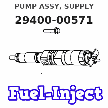
Information pump assy, supply
Rating:
Compare Prices: .
As an associate, we earn commssions on qualifying purchases through the links below

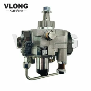
Fuel Injection Pump Compatible with Isuzu 4HK1 4HK1-TCC 4HK1-TCS 5.2L Engine FRR FSR FTR FVR FSS F-Series Trucks 294000-0570 294000-0571 8973865570 8973865575
KoovDem Part Number: 294000-0570, 294000-0571, 2940000570, 2940000571 || OEM Part Number: 8973865570, 8973865571, 8973865572, 8973865573, 8973865574, 8973865575, 8973865576, 8973865577, 8973865578, 8973865579 || The engine model is designed for Isuzu 4HK1, 4HK1-TCC, 4HK1-TCS, and 5.2L engines. || This product is tailored for Isuzu F-Series Trucks like FRR, FSR, FTR, FVR, and FSS, meeting their specifications for seamless fit and top performance. Whether you have a fleet or individual models, this product ensures optimal reliability and functionality for your trucks. || Effective and Reliable: Utilizing cutting-edge technology, this system delivers effective and reliable fuel supply, guaranteeing smooth vehicle performance.
KoovDem Part Number: 294000-0570, 294000-0571, 2940000570, 2940000571 || OEM Part Number: 8973865570, 8973865571, 8973865572, 8973865573, 8973865574, 8973865575, 8973865576, 8973865577, 8973865578, 8973865579 || The engine model is designed for Isuzu 4HK1, 4HK1-TCC, 4HK1-TCS, and 5.2L engines. || This product is tailored for Isuzu F-Series Trucks like FRR, FSR, FTR, FVR, and FSS, meeting their specifications for seamless fit and top performance. Whether you have a fleet or individual models, this product ensures optimal reliability and functionality for your trucks. || Effective and Reliable: Utilizing cutting-edge technology, this system delivers effective and reliable fuel supply, guaranteeing smooth vehicle performance.

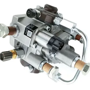
294000-0570 294000-0571 8973865570 8973865575 Fuel Injection Pump for Isuzu 4HK1 4HK1-TCC 4HK1-TCS 5.2L Engine FRR FSR FTR FVR FSS F-Series Trucks
HIRINTOL 🔸Replace Part Number: 294000-0570, 294000-0571, 2940000570, 2940000571 || 🔸OEM Part Number: 8973865570, 8973865571, 8973865572, 8973865573, 8973865574, 8973865575, 8973865576, 8973865577, 8973865578, 8973865579 || 🔸Engine Model: for Isuzu 4HK1 4HK1-TCC 4HK1-TCS 5.2L Engine || 🔸Compatible Model: for Isuzu FRR FSR FTR FVR FSS F-Series Trucks || 🔸Efficient And Stable: Using advanced technology, it can provide efficient and stable fuel supply to ensure the normal operation of the vehicle.
HIRINTOL 🔸Replace Part Number: 294000-0570, 294000-0571, 2940000570, 2940000571 || 🔸OEM Part Number: 8973865570, 8973865571, 8973865572, 8973865573, 8973865574, 8973865575, 8973865576, 8973865577, 8973865578, 8973865579 || 🔸Engine Model: for Isuzu 4HK1 4HK1-TCC 4HK1-TCS 5.2L Engine || 🔸Compatible Model: for Isuzu FRR FSR FTR FVR FSS F-Series Trucks || 🔸Efficient And Stable: Using advanced technology, it can provide efficient and stable fuel supply to ensure the normal operation of the vehicle.

High Pressure Fuel Pump 2940000570 2940000571 2940001190 2940001191 8973865570 8973865574 Compatible For ISUZU 4HK1
BKAYOLOF Ensure the stable operation of the engine: stable fuel pressure output can avoid problems such as stalling and idling during the operation of the engine to ensure the smooth operation of the engine. || Enhanced combustion efficiency: Through the generation of high pressure, the fuel atomization effect in the combustion chamber is better, the combustion is more uniform, effectively improve the combustion efficiency, and then improve the overall performance of the engine. || Optimize fuel injection: can accurately control the amount of fuel injection and injection timing, according to different engine working conditions, reasonable fuel supply, avoid fuel waste, thereby reducing fuel consumption, improve fuel economy. || Reduce harmful gas emissions: Accurate fuel injection and good combustion effect help to reduce the emissions of carbon monoxide, hydrocarbons, nitrogen oxides and other harmful gases in the engine exhaust. || High Pressure Fuel Pump 2940000570 2940000571 2940001190 2940001191 8973865570 8973865574 Compatible For ISUZU 4HK1
BKAYOLOF Ensure the stable operation of the engine: stable fuel pressure output can avoid problems such as stalling and idling during the operation of the engine to ensure the smooth operation of the engine. || Enhanced combustion efficiency: Through the generation of high pressure, the fuel atomization effect in the combustion chamber is better, the combustion is more uniform, effectively improve the combustion efficiency, and then improve the overall performance of the engine. || Optimize fuel injection: can accurately control the amount of fuel injection and injection timing, according to different engine working conditions, reasonable fuel supply, avoid fuel waste, thereby reducing fuel consumption, improve fuel economy. || Reduce harmful gas emissions: Accurate fuel injection and good combustion effect help to reduce the emissions of carbon monoxide, hydrocarbons, nitrogen oxides and other harmful gases in the engine exhaust. || High Pressure Fuel Pump 2940000570 2940000571 2940001190 2940001191 8973865570 8973865574 Compatible For ISUZU 4HK1
You can express buy:
USD 497
13-05-2025
13-05-2025
HP3 High Pressure Fuel Pump For ISUZU 4HK1 Diesel Pump 294000-0570 294000-0571 294000-1190 294000-1191 8-97386557-0 8-97386557-4
USD 422.03
19-05-2025
19-05-2025
Common Rail Fuel Injection Pump 294000-1190 294000-1191 294000-0571 8973865575 for ISUZU 4hk1Engine
USD 396.61
19-05-2025
19-05-2025
Diesel fuel pump engine fuel pump 294000-0574 8-97386557-1 294000-0571 294000-0572 8-97386557-2 294000-0573
Images:
USD 423.29

[19-May-2025]
USD 401.22

[19-May-2025]
USD 401.22

[19-May-2025]
USD 380.32

[02-May-2025]
Components :
| 001. | PUMP ASSY, SUPPLY | 29400-00571 |
| 001. | PUMP ASSY, SUPPLY | 29400-00571 |
| 001. | PUMP ASSY, SUPPLY | 29400-00571 |
| 001. | PUMP ASSY, SUPPLY | 29400-00571 |
| 002. | OVERHAUL KIT, SUPP | 29400-90031 |
| 003. | OVERHAUL KIT, SUPP | 29400-91150 |
Scheme ###:

| 000. | [01] | 29400-00571 | PUMP ASSY, SUPPLY | 1K0B 13 800 |
| 000. | [01] | 29400-00572 | PUMP ASSY, SUPPLY | |
| 000. | [01] | 29400-00573 | PUMP ASSY, SUPPLY | |
| 001. | [01] | 29410-00680 | HOUSING SUB-ASSY, | |
| 002. | [02] | 29417-80040 | WASHER, CAMSHAFT | |
| 003. | [01] | 29419-10010 | CAMSHAFT, SUPPLY P | |
| 004. | [01] | 29402-10020 | KEY, WOODRUFF | |
| 005. | [01] | 29417-00120 | RING SUB-ASSY, CAM | |
| 005. | [01] | 29417-00010 | RING SUB-ASSY, CAM | |
| 006. | [01] | 29412-00270 | COVER SUB-ASSY, BE | |
| 006. | [01] | 29412-00310 | COVER SUB-ASSY, BE | |
| 006-001. | [01] | 29419-70010 | SEAL, OIL | |
| 007. | [06] | 29419-90050 | BOLT, SOCKET | |
| 008. | [01] | 29419-80050 | O-RING, SUPPLY PUM | |
| 009. | [02] | 29419-80030 | O-RING, SUPPLY PUM | |
| 010. | [01] | 29418-30170 | PLATE, FEED PUMP, | |
| 011. | [01] | 29418-40140 | COVER, FEED PUMP | |
| 012. | [01] | 29418-70010 | KEY, FEED PUMP | |
| 012. | [01] | 29418-70040 | KEY, FEED PUMP | |
| 013. | [01] | 29418-00080 | ROTOR SET, FEED PU | |
| 014. | [05] | 29419-90040 | BOLT, SOCKET | |
| 015. | [01] | 29409-00190 | ELEMENT KIT, SUPPL | |
| 015. | [01] | 29409-00370 | ELEMENT KIT, SUPPL | |
| 016. | [01] | 29409-00110 | ELEMENT KIT, SUPPL | |
| 016. | [01] | 29409-00300 | ELEMENT KIT, SUPPL | |
| 017. | [02] | 29415-90040 | SPRING, PLUNGER | |
| 018. | [02] | 29419-80010 | O-RING, SUPPLY PUM | |
| 019. | [02] | 29419-80040 | O-RING, SUPPLY PUM | |
| 020. | [06] | 29419-90060 | BOLT, SOCKET | |
| 021. | [02] | 29414-00082 | VALVE SUB-ASSY, SU | |
| 022. | [02] | 29419-80020 | O-RING, SUPPLY PUM | |
| 023. | [02] | 29413-50010 | PLUG, CYLINDER | |
| 031. | [01] | 09806-60030 | O-RING, DISTRIBUTI | TF88 13 TS2 |
| 032. | [01] | 17973-00100 | SENSOR, FUEL TEMPE | |
| 033. | [01] | 29420-00170 | VALVE ASSY, SUCTIO | |
| 033. | [01] | 29420-00370 | VALVE ASSY, SUCTIO | |
| 033-001. | [01] | 29428-60030 | O-RING, VALVE | |
| 034. | [01] | 29428-50040 | O-RING, SOLENOID | |
| 035. | [01] | 29416-00011 | VALVE SUB-ASSY, RE | |
| 035. | [01] | 29416-00130 | VALVE SUB-ASSY, RE | |
| 035-001. | [01] | 29419-80060 | O-RING, SUPPLY PUM | |
| 035-002. | [01] | 29419-80070 | O-RING, SUPPLY PUM | |
| 036. | [01] | 29401-00200 | PIPE, SUPPLY PUMP | |
| 036. | [01] | 29401-00120 | PIPE, SUPPLY PUMP | |
| 037. | [02] | 29416-90010 | PIN, STOPPER | |
| 038. | [01] | 29411-50040 | PLUG, FILTER | |
| 039. | [01] | 29411-70010 | GASKET, PLUG | |
| 040. | [01] | 09737-00010 | FILTER SUB-ASSY | |
| 041. | [01] | 09604-90460 | O-RING | |
| 042. | [01] | 29425-90020 | GASKET, SOLENOID | |
| 044. | [01] | 09543-80170 | SCREW, HOLLOW | |
| 044. | [01] | 09543-80010 | SCREW, HOLLOW | |
| 045. | [02] | 94901-02530 | WASHER | |
| 046. | [01] | 94919-80260 | COLLAR, PRESSBOARD | 0727 24 422 |
| 047. | [01] | 94918-00310 | SCREW, HOLLOW | |
| 048. | [02] | 94901-02490 | WASHER | |
| 049. | [01] | 94919-80270 | COLLAR, PRESSBOARD | |
| 052. | [01] | 09001-40160 | CAP, VALVE HOLDER | |
| 101. | [01] | 29400-90010 | OVERHAUL KIT, SUPP | |
| 102. | [01] | 29400-90100 | OVERHAUL KIT, SUPP | |
| 200. | [01] | 29400-90031 | OVERHAUL KIT, SUPP | |
| 201. | [02] | 29400-90370 | OVERHAUL KIT, SUPP | |
| 202. | [01] | 29400-91150 | OVERHAUL KIT, SUPP | |
| 300. | [01] | 29409-05000 | ELEMENT KIT, SUPPL | |
| 301. | [01] | 29409-05010 | ELEMENT KIT, SUPPL | |
| 302. | [01] | 29413-10220 | HOLDER, DELIVERY V |
Include in #3:
Cross reference number
| Part num | Firm num | Firm | Name |
| 29400-00571 | PUMP ASSY, SUPPLY |
Information:
start by:a) remove turbocharger 1. Put the turbocharger in position on tool (A).2. Put a mark on the compressor cover and housings for installation purpose.3. Remove bolts (1) and plates from compressor housing.4. Remove the compressor housing. 5. Remove bolts (2) and locks from turbine housing. 6. Remove cartridge (3) from turbine housing.7. Install tool (B) in tool (C). Install cartridge in tool (C).8. Remove nut (4) from the compressor wheel.
When the nut is loosened, do not put a side force on the shaft.
9. Install tool (D) on an oil heater. Heat the oil to 350°F (177°C). Install the cartridge on tool (D) with only the compressor wheel in the hot oil. Keep the compressor wheel in the hot oil for ten minutes. 10. Put tool (D) and cartridge on tool (E) under a press. Install driver (F) and push the shaft out of the compressor wheel. Step 10 must be done before the compressor wheel gets cold.11. Remove compressor wheel and shroud. Remove turbine wheel and shaft. 12. Remove the four bolts (5) and locks from plate (6). 13. Remove plate (6), spacer, collar and thrust bearing from cartridge.14. Remove seal from plate and ring from spacer. 15. Remove bearing (7), washer (11) and snap ring (8) from compressor side of cartridge.16. Remove snap ring (13), washer (10), bearing (12) and snap ring (9) from turbine side of cartridge.17. Check all the parts of the turbocharger for damage. If the parts have damage, use new parts for replacement. See SPECIAL INSTRUCTION, Form No. SMHS6854 for TURBOCHARGER RECONDITIONING. Also see GUIDELINE FOR REUSABLE PARTS, Form No. SEBF8018.Assemble Turbocharger (Airesearch T18)
1. Make sure all oil passages are open and clean. Put clean engine oil on all parts before assembly 2. Install snap ring (6), bearing (3), washer (7) and snap ring (4) in turbine side of cartridge. Install the two snap rings with tool (A). Install the snap rings with the rounded edge toward the bearing.3. Install snap ring (2), washer (5) and bearing (1) in compressor side of cartridge. 4. Install seal (12) on plate (8) and ring (9) on spacer.5. Install collar (10) in plate and spacer (11) in collar. 6. Install thrust bearing (13) with the three radial grooves toward the outside.7. Install plate (8), bolts and locks. Tighten bolts to a torque of 35 5 lb. in. (4.0 0.6 N m). Put 6V2055 High Vacuum Grease in the groove for seal ring (14) at assembly to one half or more of the depth of the groove all the way around.8. Install ring (14) on turbine wheel.9. Install turbine wheel and shaft in cartridge. Be careful not to break ring (14) when installing shaft. 10. Put cartridge on tool (C) and tool (C) on tool (B). Some compressor wheels (15) can be installed at room temperature. If the compressor wheel will go on the turbine shaft freely to within .31 in. (7.9 mm) of the seal carrier the compressor wheel can be installed at