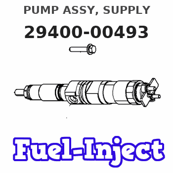
Information pump assy, supply
Rating:
Compare Prices: .
As an associate, we earn commssions on qualifying purchases through the links below

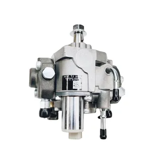
294000-0493 294000-0492 294000-0491 294000-0490 8-97381555-0 8-97381555-1 HP3 Fuel Injection Pump Suitable for Isuzu 4JJ1 4JJ1-TC 4JJ1-TCX 3.0L Engine NHR NPR NRR NQR N Series Trucks
OfkZynodor Part Name:Fuel Injection Pump || Part Number:294000-0493 294000-0492 294000-0491 294000-0490 8-97381555-0 8-97381555-1 || Application:Suitable for Isuzu 4JJ1 4JJ1-TC 4JJ1-TCX 3.0L Engine NHR NPR NRR NQR N Series Trucks || Please make sure to carefully compare the photos and check the part numbers before making the purchase. If you are unable to confirm your engine model or part number, please leave us a message and we will assist you in confirming that the product you purchase is the one you need. || Your order is not merely a single purchase but the beginning of a cooperative journey, aiming to ensure the safe and smooth operation of your vehicle. We are proud to offer you reliable precision engineering components and unparalleled services.
OfkZynodor Part Name:Fuel Injection Pump || Part Number:294000-0493 294000-0492 294000-0491 294000-0490 8-97381555-0 8-97381555-1 || Application:Suitable for Isuzu 4JJ1 4JJ1-TC 4JJ1-TCX 3.0L Engine NHR NPR NRR NQR N Series Trucks || Please make sure to carefully compare the photos and check the part numbers before making the purchase. If you are unable to confirm your engine model or part number, please leave us a message and we will assist you in confirming that the product you purchase is the one you need. || Your order is not merely a single purchase but the beginning of a cooperative journey, aiming to ensure the safe and smooth operation of your vehicle. We are proud to offer you reliable precision engineering components and unparalleled services.
294000-0493 294000-0492 294000-0491 294000-0490 8-97381555-0 8-97381555-1 HP3 Fuel Injection Pump Suitable for Isuzu 4JJ1 4JJ1-TC 4JJ1-TCX 3.0L Engine NHR NPR NRR NQR N Series Trucks
Yuubryczny Part Name:Fuel Injection Pump || Part Number:294000-0493 294000-0492 294000-0491 294000-0490 8-97381555-0 8-97381555-1 || Application:Suitable for Isuzu 4JJ1 4JJ1-TC 4JJ1-TCX 3.0L Engine NHR NPR NRR NQR N Series Trucks || Precise matching is the first step towards safe driving! To ensure that the accessories fit perfectly with your beloved car, please make sure to check the product details page before placing an order or contact us privately. Your meticulousness is the best guarantee for driving safety! || "Thank you for your trust and support! If you have any questions regarding the products, please feel free to contact us at any time. We will do our best to solve them for you. Wish you a pleasant experience!"
Yuubryczny Part Name:Fuel Injection Pump || Part Number:294000-0493 294000-0492 294000-0491 294000-0490 8-97381555-0 8-97381555-1 || Application:Suitable for Isuzu 4JJ1 4JJ1-TC 4JJ1-TCX 3.0L Engine NHR NPR NRR NQR N Series Trucks || Precise matching is the first step towards safe driving! To ensure that the accessories fit perfectly with your beloved car, please make sure to check the product details page before placing an order or contact us privately. Your meticulousness is the best guarantee for driving safety! || "Thank you for your trust and support! If you have any questions regarding the products, please feel free to contact us at any time. We will do our best to solve them for you. Wish you a pleasant experience!"

HP3 Fuel Injection Pump Compatible with Isuzu 4JJ1 4JJ1-TC 4JJ1-TCX 3.0L Engine NHR NPR NRR NQR N Series Trucks 294000-0493 294000-0492 294000-0491 294000-0490 8-97381555-0 8-97381555-1
KoovDem Part Number: 294000-0493, 294000-0492, 294000-0491, 294000-0490, 8-97381555-0, 8-97381555-1, 8-97381555-2, 8-97381555-3, 8-97381555-4, 8-97381555-5, 8-97381555-6, 8-97381555-7, 8-97381555-8, 8-97381555-9. || Engine Model: For Isuzu 4JJ1 4JJ1-TC 4JJ1-TCX 3.0L NHR NPR NRR NQR N Series Trucks. || Compatible with John Deere Tractor model 750. || Effective and Reliable: Utilizing cutting-edge technology, this system delivers effective and reliable fuel supply, guaranteeing smooth vehicle performance. || Rugged and Dependable: With a track record of being rigorously tested and proven, this product offers durability and reliability, ensuring it operates consistently even in the harshest of environments.
KoovDem Part Number: 294000-0493, 294000-0492, 294000-0491, 294000-0490, 8-97381555-0, 8-97381555-1, 8-97381555-2, 8-97381555-3, 8-97381555-4, 8-97381555-5, 8-97381555-6, 8-97381555-7, 8-97381555-8, 8-97381555-9. || Engine Model: For Isuzu 4JJ1 4JJ1-TC 4JJ1-TCX 3.0L NHR NPR NRR NQR N Series Trucks. || Compatible with John Deere Tractor model 750. || Effective and Reliable: Utilizing cutting-edge technology, this system delivers effective and reliable fuel supply, guaranteeing smooth vehicle performance. || Rugged and Dependable: With a track record of being rigorously tested and proven, this product offers durability and reliability, ensuring it operates consistently even in the harshest of environments.
You can express buy:
USD 393.14
13-05-2025
13-05-2025
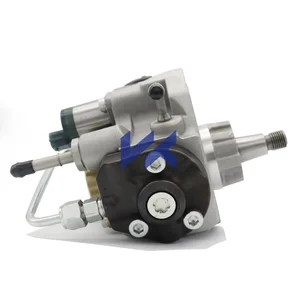
Diesel Common Rail Fuel Pump 294000-0490 294000-0493 8-97381555-6 For ISUZU Engine
USD 521.62
19-05-2025
19-05-2025
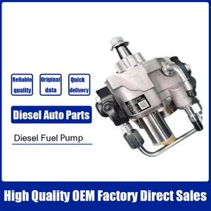
Injector Pump diese Engine Fuel Pump 294000-0493 2940000493 for ISUZU 4JJ1 8-97381555-3
USD 475.74
12-05-2025
12-05-2025
Diesel Common Rail Fuel Pump 294000-0490 294000-0493 8-97381555-6 For ISUZU Engine
Images:
USD 559.39

[27-May-2025]
USD 384.18

[19-May-2025]
USD 486.85

[30-May-2025]
USD 462
[01-Jun-2025]
Scheme ###:

| 000. | [01] | 29400-00491 | PUMP ASSY, SUPPLY | 8-97381555-1 |
| 000. | [01] | 29400-00492 | PUMP ASSY, SUPPLY | 8-97381555-2 |
| 000. | [01] | 29400-00493 | PUMP ASSY, SUPPLY | 8-97381555-3 |
| 001. | [01] | 29410-00632 | HOUSING SUB-ASSY, | |
| 002. | [02] | 29417-80040 | WASHER, CAMSHAFT | |
| 003. | [01] | 29419-10010 | CAMSHAFT, SUPPLY P | |
| 004. | [01] | 29402-10020 | KEY, WOODRUFF | |
| 005. | [01] | 29417-00120 | RING SUB-ASSY, CAM | |
| 005. | [01] | 29417-00010 | RING SUB-ASSY, CAM | |
| 006. | [01] | 29412-00270 | COVER SUB-ASSY, BE | |
| 006. | [01] | 29412-00310 | COVER SUB-ASSY, BE | |
| 006-001. | [01] | 29419-70010 | SEAL, OIL | |
| 007. | [06] | 09644-90110 | BOLT, SOCKET | 8-97140853-0 |
| 008. | [01] | 29419-80050 | O-RING, SUPPLY PUM | |
| 009. | [02] | 29419-80030 | O-RING, SUPPLY PUM | |
| 010. | [01] | 29418-30160 | PLATE, FEED PUMP, | |
| 011. | [01] | 29418-40080 | COVER, FEED PUMP | |
| 012. | [01] | 29418-70010 | KEY, FEED PUMP | |
| 012. | [01] | 29418-70040 | KEY, FEED PUMP | |
| 013. | [01] | 29418-00080 | ROTOR SET, FEED PU | |
| 014. | [05] | 09644-90050 | BOLT, SOCKET | |
| 015. | [01] | 29409-00180 | ELEMENT KIT, SUPPL | |
| 015. | [01] | 29409-00400 | ELEMENT KIT, SUPPL | |
| 016. | [01] | 29409-00160 | ELEMENT KIT, SUPPL | |
| 016. | [01] | 29409-00090 | ELEMENT KIT, SUPPL | |
| 017. | [02] | 29415-90040 | SPRING, PLUNGER | |
| 018. | [02] | 29419-80010 | O-RING, SUPPLY PUM | |
| 019. | [02] | 29419-80040 | O-RING, SUPPLY PUM | |
| 020. | [06] | 29419-90010 | BOLT, SOCKET | |
| 021. | [02] | 29414-00082 | VALVE SUB-ASSY, SU | |
| 022. | [02] | 29419-80020 | O-RING, SUPPLY PUM | |
| 023. | [02] | 29413-50010 | PLUG, CYLINDER | |
| 031. | [01] | 09806-60030 | O-RING, DISTRIBUTI | |
| 032. | [01] | 17973-00100 | SENSOR, FUEL TEMPE | |
| 033. | [01] | 29420-00170 | VALVE ASSY, SUCTIO | |
| 033. | [01] | 29420-00370 | VALVE ASSY, SUCTIO | |
| 033-001. | [01] | 29428-60030 | O-RING, VALVE | |
| 034. | [01] | 29428-50040 | O-RING, SOLENOID | |
| 035. | [01] | 29416-00130 | VALVE SUB-ASSY, RE | |
| 035. | [01] | 29416-00011 | VALVE SUB-ASSY, RE | |
| 035-001. | [01] | 29419-80060 | O-RING, SUPPLY PUM | |
| 035-002. | [01] | 29419-80070 | O-RING, SUPPLY PUM | |
| 036. | [01] | 29401-00130 | PIPE, SUPPLY PUMP | |
| 037. | [02] | 29416-90010 | PIN, STOPPER | |
| 038. | [01] | 29411-50010 | PLUG, FILTER | |
| 039. | [01] | 29411-70010 | GASKET, PLUG | |
| 040. | [01] | 09737-00010 | FILTER SUB-ASSY | |
| 041. | [01] | 09604-90460 | O-RING | |
| 043. | [01] | 29425-90020 | GASKET, SOLENOID | |
| 044. | [01] | 94918-00060 | SCREW, HOLLOW | 9-88130088-0 |
| 045. | [02] | 94901-02470 | WASHER | 1-15619508-0 |
| 046. | [01] | 94919-80260 | COLLAR, PRESSBOARD | |
| 052. | [01] | 09001-40160 | CAP, VALVE HOLDER | |
| 053. | [01] | 09748-60020 | CAP, RUBBER | |
| 101. | [01] | 29400-90010 | OVERHAUL KIT, SUPP | |
| 102. | [01] | 29400-90100 | OVERHAUL KIT, SUPP | |
| 200. | [01] | 29400-90031 | OVERHAUL KIT, SUPP | |
| 201. | [02] | 29400-90370 | OVERHAUL KIT, SUPP | |
| 202. | [01] | 29400-91140 | OVERHAUL KIT, SUPP | |
| 300. | [01] | 29409-05010 | ELEMENT KIT, SUPPL | |
| 301. | [01] | 29409-05020 | ELEMENT KIT, SUPPL | |
| 302. | [01] | 29413-10080 | HOLDER, DELIVERY V | |
| 303. | [01] | 29413-10220 | HOLDER, DELIVERY V |
Include in #3:
Cross reference number
| Part num | Firm num | Firm | Name |
| 29400-00493 | PUMP ASSY, SUPPLY |
Information:
Engine Design
CYLINDER AND VALVE LOCATIONBore ... 5.40 in.(137.2 mm)Stroke ... 6.50 in.(165.1 mm)Number and Arrangement of Cylinders ... 6, In LineFiring Order (Injection Sequence) ... 1, 5, 3, 6, 2, 4No. 1 Cylinder Location ... FrontRotation of Crankshaft (when seen from flywheel end) ... counterclockwiseRotation of Fuel Pump Camshaft (when seen from pump drive end) ... counterclockwiseFuel System
FUEL SYSTEM
1. Injection valve. 2. Anti-siphon block. 3. Injection pump housing. 4. Priming pump. 5. Plug. 6. Secondary filter. 7. Fuel line. 8. Return line to tank. 9. Fuel tank. 10. Primary filter. 11. Transfer pump.This engine has a pressure type fuel system. There is a single injection pump and injection valve (1) for each cylinder. The injection pumps are in the pump housing (3) on the left side of the engine. The injection valves (1) are in the precombustion chambers or adapters under the valve cover.The transfer pump (11) pulls fuel from the fuel tank (9) through the primary filter (10) and sends it through the base of priming pump (4) and the secondary filter (6), through the anti-siphon block (2) and to the manifold of the injection pump housing. When priming pump (4) is not used, the position of fuel line (7) and plug (5) are reversed. The fuel in the manifold of the injection pump housing goes to the injection pumps. The injection pumps are in time with the engine and send fuel to the injection valves under high pressure.Some of the fuel in the manifold is constantly sent back through the anti-siphon block (2) and through the return line (8) to the fuel tank to remove air from the system. Orifices in the anti-siphon block control the amount of fuel that goes back to the fuel tank.The priming pump (4) is used to remove air from the fuel filter, fuel lines and components.The transfer pump has a bypass valve and a check valve. The bypass valve (lower side) gives control to the pressure of the fuel. The extra fuel goes to the inlet of the pump.Fuel Injection Pump Operation
Injection pump plungers (4) and lifters (8) are lifted by cams on camshaft (9) and always make a full stroke. The force of springs (5) hold the lifters (8) against the cams of the camshaft.Fuel from fuel manifold (1) goes through inlet passage (2) in the barrel and then into the chamber above plunger (4). During injection, the camshaft cam moves plunger (4) up in the barrel. This movement will close inlet passage (2) and push the fuel out through the fuel lines to the injection valves.The amount of fuel sent to the injection valves is controlled by turning plunger (4) in the barrel. When the governor moves fuel rack (7), the fuel rack moves gear (6) that is fastened to the bottom of plunger (4).
CROSS SECTION OF THE HOUSING FOR THE FUEL INJECTION PUMPS
1. Fuel manifold. 2. Inlet passage in pump barrel. 3. Check valve. 4. Pump plunger. 5. Spring. 6. Gear. 7. Fuel rack. 8. Lifter. 9.