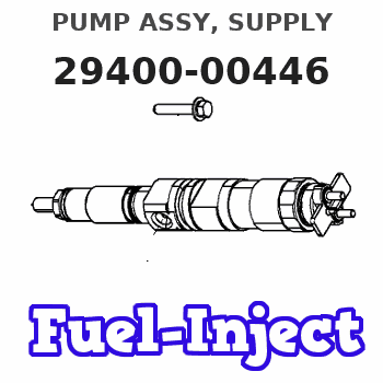
Information pump assy, supply
Rating:
Compare Prices: .
As an associate, we earn commssions on qualifying purchases through the links below

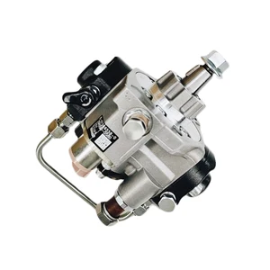
294000-0446 Diesel Engine Component Fuel Injection Pump 。Compatible For Truck
BMDFHJ Made with durable materials that can withstand harsh operating conditions, providing long-lasting reliability and efficiency. || Improved fuel delivery and engine performance can help improve fuel economy and reduce emissions, reduce carbon deposits and wear, and keep engines running efficiently. || Ideal for heavy-duty applications, very engine-powered trucks, buses, and industrial machinery. || Allows the engine to quickly get the amount of fuel it needs when accelerating or changing loads, resulting in higher power output. || Automatically adjusts fuel injection to improve engine performance and responsiveness, precise fuel injection for improved engine combustion efficiency.
BMDFHJ Made with durable materials that can withstand harsh operating conditions, providing long-lasting reliability and efficiency. || Improved fuel delivery and engine performance can help improve fuel economy and reduce emissions, reduce carbon deposits and wear, and keep engines running efficiently. || Ideal for heavy-duty applications, very engine-powered trucks, buses, and industrial machinery. || Allows the engine to quickly get the amount of fuel it needs when accelerating or changing loads, resulting in higher power output. || Automatically adjusts fuel injection to improve engine performance and responsiveness, precise fuel injection for improved engine combustion efficiency.

Aftermarket Fuel Injection Pump 294000-0446 22100-0L030 Fit Intended For Engine 2KD-FTV Vehicle
Generic Motorcycle Parts || Heavy Equipment Parts || Spare Parts || Fuel Systems
Generic Motorcycle Parts || Heavy Equipment Parts || Spare Parts || Fuel Systems

Fuel Pump 294000-0446 Engine Oil Pump
DFGUFG [OE NO. & Part NO] 294000-0446 || [Product Name and Model] Fuel Injection Pump || [Easy Installation] Standardized interface design, no additional modification required, simple and quick installation process, users can easily complete replacement and maintenance. || [Quality Assurance] Products undergo rigorous quality testing to ensure reliable performance and high-quality after-sales service, so you have no worries. || [Reliable Performance] Provides excellent fuel injection performance, optimizes engine operating efficiency, and helps equipment operate stably for a long time.
DFGUFG [OE NO. & Part NO] 294000-0446 || [Product Name and Model] Fuel Injection Pump || [Easy Installation] Standardized interface design, no additional modification required, simple and quick installation process, users can easily complete replacement and maintenance. || [Quality Assurance] Products undergo rigorous quality testing to ensure reliable performance and high-quality after-sales service, so you have no worries. || [Reliable Performance] Provides excellent fuel injection performance, optimizes engine operating efficiency, and helps equipment operate stably for a long time.
You can express buy:
USD 393.14
13-05-2025
13-05-2025
Diesel Common Rail Fuel Pump 294000-0446 22100-0L030 For Truck
Scheme ###:

| 000. | [01] | 29400-00446 | PUMP ASSY, SUPPLY | 22100-0L030 |
| 001. | [01] | 29410-00561 | HOUSING SUB-ASSY, | SM |
| 002. | [02] | 29417-80060 | WASHER, CAMSHAFT | SM |
| 003. | [01] | 29419-10050 | CAMSHAFT, SUPPLY P | SM |
| 004. | [01] | 29402-10020 | KEY, WOODRUFF | |
| 005. | [01] | 29417-00240 | RING SUB-ASSY, CAM | SM |
| 005. | [01] | 29417-00130 | RING SUB-ASSY, CAM | SM |
| 006. | [01] | 29412-00250 | COVER SUB-ASSY, BE | SM |
| 006. | [01] | 29412-00330 | COVER SUB-ASSY, BE | SM |
| 006-001. | [01] | 29419-70010 | SEAL, OIL | |
| 007. | [06] | 09644-90380 | BOLT, SOCKET | SM |
| 008. | [01] | 29419-80120 | O-RING, SUPPLY PUM | SM |
| 009. | [02] | 29419-80100 | O-RING, SUPPLY PUM | SM |
| 010. | [01] | 29418-30141 | PLATE, FEED PUMP, | SM |
| 011. | [01] | 29418-40120 | COVER, FEED PUMP | SM |
| 012. | [01] | 29418-70010 | KEY, FEED PUMP | |
| 013. | [01] | 29418-00090 | ROTOR SET, FEED PU | SM |
| 014. | [05] | 09644-90370 | BOLT, SOCKET | SM |
| 015. | [01] | 29409-00150 | ELEMENT KIT, SUPPL | SM |
| 016. | [01] | 29409-00160 | ELEMENT KIT, SUPPL | SM |
| 017. | [02] | 29415-90040 | SPRING, PLUNGER | |
| 018. | [02] | 29419-80080 | O-RING, SUPPLY PUM | SM |
| 019. | [02] | 29419-80110 | O-RING, SUPPLY PUM | SM |
| 020. | [06] | 29419-90030 | BOLT, SOCKET | SM |
| 031. | [01] | 29419-80150 | O-RING, SUPPLY PUM | SM |
| 032. | [01] | 17973-00020 | SENSOR, FUEL TEMPE | 89454-60010 |
| 032. | [01] | 17973-00100 | SENSOR, FUEL TEMPE | 89454-20010 |
| 033. | [01] | 29420-00093 | VALVE ASSY, SUCTIO | SM |
| 033. | [01] | 29420-00300 | VALVE ASSY, SUCTIO | SM |
| 033-001. | [01] | 29428-60030 | O-RING, VALVE | SM |
| 034. | [01] | 29428-50030 | O-RING, SOLENOID | SM |
| 035. | [01] | 29416-00130 | VALVE SUB-ASSY, RE | SM |
| 035. | [01] | 29416-00071 | VALVE SUB-ASSY, RE | SM |
| 035-001. | [01] | 29419-80130 | O-RING, SUPPLY PUM | SM |
| 035-002. | [01] | 29419-80140 | O-RING, SUPPLY PUM | SM |
| 036. | [01] | 29401-00071 | PIPE, SUPPLY PUMP | SM |
| 037. | [02] | 29416-90010 | PIN, STOPPER | |
| 038. | [01] | 29411-50031 | PLUG, FILTER | SM |
| 039. | [01] | 29411-70020 | GASKET, PLUG | SM |
| 040. | [01] | 09737-00050 | FILTER SUB-ASSY | SM |
| 041. | [01] | 29419-80160 | O-RING, SUPPLY PUM | SM |
| 043. | [01] | 29425-90020 | GASKET, SOLENOID | |
| 052. | [01] | 09001-45170 | CAP, VALVE HOLDER | SM |
| 053. | [01] | 09808-10100 | COVER, RUBBER | SM |
| 054. | [01] | 09808-10110 | COVER, RUBBER | SM |
| 101. | [01] | 29400-90010 | OVERHAUL KIT, SUPP | SM |
| 102. | [01] | 29400-90020 | OVERHAUL KIT, SUPP | SM |
| 200. | [01] | 29400-90080 | OVERHAUL KIT, SUPP | SM |
| 201. | [01] | 29400-90460 | OVERHAUL KIT, SUPP | SM |
Include in #3:
29400-00446
as PUMP ASSY, SUPPLY
Cross reference number
| Part num | Firm num | Firm | Name |
| 29400-00446 | 22100-0L03 | PUMP ASSY, SUPPLY |
Information:
4. Remove the camshaft driveshaft cover at the top of the flywheel housing. Install a 3/8" - 16 NC forged eyebolt in the driveshaft (3) and remove the driveshaft. On engines with a BrakeSaver, remove two plugs (4) from the flywheel housing.5. Disconnect glow plug wiring harness from the glow plugs and valve cover base. Remove the inner fuel injection lines. Put plugs or caps on all fuel lines and openings. 6. Remove the fifteen other bolts and locks (seven each side and one in rear). Remove two of the glow plug wiring harness mounting bolts and install two 3/8" - 16 NC forged eyebolts. Pull the camshafts (5) off dowels. Fasten a hoist and remove the camshafts (5). Weight of the camshafts is 100 lb. (45 kg).Install Camshafts
1. Adjust all of the camshaft followers to give maximum clearance. 2. Put the camshaft phasing gear timing marks (1) together and in a horizontal plane. 3. Install two 3/8" - 16 forged eyebolts. Fasten a hoist and install the camshafts (2) on the engine. Install the camshaft retaining bolts and locks.
Never install the camshafts if the No. 1 piston is not at top center on the compression stroke. Damage to the engine can be the result if No. 1 piston is not in correct position.
4. Remove the eyebolts and install the glow plug wiring harness mounting bolts.5. Install the inner fuel injection lines. Tighten retaining nuts to 30 5 lb.ft. (40.7 6.8 N m).6. Connect the glow plug wiring to the plugs and to the valve cover base.7. Install the camshaft driveshaft with the alignment (blind) spline on top. Install driveshaft cover.8. Remove the timing bolt from the flywheel. Install the plug in the flywheel housing and timing bolt in the cover.9. Adjust the inlet valve clearance to .018 in. (0.46 mm) and the exhaust valve clearance to .030 in. (0.76 mm). 10. Install the valve cover (3) and the tube (4) from the turbocharger to the aftercooler.