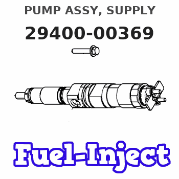
Information pump assy, supply
Rating:
You can express buy:
USD 116.34
02-06-2025
02-06-2025
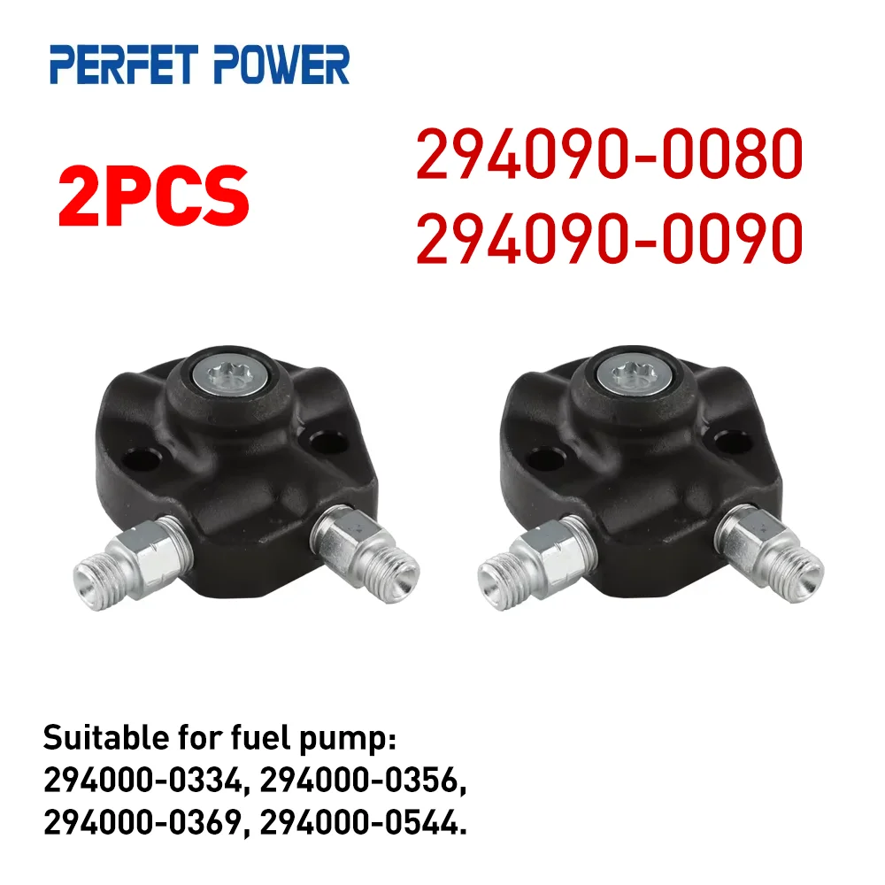
2PCS 294090-0080, 294090-0090 Pump Plunger for HP3 Fuel Pump 294000-0334, 294000-0356, 294000-0369, 294000-0544
Scheme ###:

| 000. | [01] | 29400-00369 | PUMP ASSY, SUPPLY | |
| 001. | [01] | 29410-00450 | HOUSING SUB-ASSY, | |
| 001. | [01] | 29410-00551 | HOUSING SUB-ASSY, | |
| 002. | [02] | 29417-80040 | WASHER, CAMSHAFT | |
| 003. | [01] | 29419-10010 | CAMSHAFT, SUPPLY P | |
| 004. | [01] | 29402-10020 | KEY, WOODRUFF | |
| 005. | [01] | 29417-00210 | RING SUB-ASSY, CAM | |
| 005. | [01] | 29417-00120 | RING SUB-ASSY, CAM | |
| 005. | [01] | 29417-00010 | RING SUB-ASSY, CAM | |
| 006. | [01] | 29412-00021 | COVER SUB-ASSY, BE | |
| 006. | [01] | 29412-00230 | COVER SUB-ASSY, BE | |
| 006. | [01] | 29412-00310 | COVER SUB-ASSY, BE | |
| 006-001. | [01] | 29419-70010 | SEAL, OIL | |
| 007. | [06] | 09644-90110 | BOLT, SOCKET | 22395-56351 |
| 008. | [01] | 29419-80050 | O-RING, SUPPLY PUM | |
| 009. | [02] | 29419-80030 | O-RING, SUPPLY PUM | |
| 010. | [01] | 29418-30030 | PLATE, FEED PUMP, | |
| 010. | [01] | 29418-30160 | PLATE, FEED PUMP, | |
| 011. | [01] | 29418-40080 | COVER, FEED PUMP | |
| 012. | [01] | 29418-70010 | KEY, FEED PUMP | |
| 013. | [01] | 29418-00080 | ROTOR SET, FEED PU | |
| 014. | [05] | 09644-90050 | BOLT, SOCKET | 22395-54270 |
| 015. | [01] | 29409-00080 | ELEMENT KIT, SUPPL | |
| 016. | [01] | 29409-00090 | ELEMENT KIT, SUPPL | |
| 017. | [02] | 29415-90040 | SPRING, PLUNGER | |
| 018. | [02] | 29419-80010 | O-RING, SUPPLY PUM | |
| 019. | [02] | 29419-80040 | O-RING, SUPPLY PUM | |
| 020. | [06] | 29419-90010 | BOLT, SOCKET | |
| 021. | [02] | 29414-00110 | VALVE SUB-ASSY, SU | |
| 022. | [02] | 29419-80020 | O-RING, SUPPLY PUM | |
| 023. | [02] | 29413-50011 | PLUG, CYLINDER | |
| 031. | [01] | 09806-60030 | O-RING, DISTRIBUTI | 22193-1C170 |
| 032. | [01] | 17973-00020 | SENSOR, FUEL TEMPE | 89454-60010 |
| 032. | [01] | 17973-00100 | SENSOR, FUEL TEMPE | 89454-20010 |
| 033. | [01] | 29420-00093 | VALVE ASSY, SUCTIO | |
| 033. | [01] | 29420-00300 | VALVE ASSY, SUCTIO | |
| 033-001. | [01] | 29428-60030 | O-RING, VALVE | |
| 034. | [01] | 29428-50040 | O-RING, SOLENOID | |
| 035. | [01] | 29416-00011 | VALVE SUB-ASSY, RE | |
| 035. | [01] | 29416-00130 | VALVE SUB-ASSY, RE | |
| 035-001. | [01] | 29419-80060 | O-RING, SUPPLY PUM | |
| 035-002. | [01] | 29419-80070 | O-RING, SUPPLY PUM | |
| 036. | [01] | 29401-00110 | PIPE, SUPPLY PUMP | |
| 037. | [02] | 29416-90010 | PIN, STOPPER | |
| 038. | [01] | 29411-50010 | PLUG, FILTER | |
| 039. | [01] | 29411-70010 | GASKET, PLUG | |
| 040. | [01] | 09737-00010 | FILTER SUB-ASSY | |
| 041. | [01] | 09604-90460 | O-RING | 22193-5B320 |
| 043. | [01] | 29425-90020 | GASKET, SOLENOID | |
| 101. | [01] | 29400-90010 | OVERHAUL KIT, SUPP | |
| 102. | [01] | 29400-90020 | OVERHAUL KIT, SUPP | |
| 102. | [01] | 29400-90100 | OVERHAUL KIT, SUPP | |
| 200. | [01] | 29400-91200 | OVERHAUL KIT, SUPP | |
| 200. | [01] | 29400-90031 | OVERHAUL KIT, SUPP | |
| 201. | [01] | 29400-90280 | OVERHAUL KIT, SUPP | |
| 202. | [02] | 29400-90540 | OVERHAUL KIT, SUPP | |
| 300. | [01] | 29409-05010 | ELEMENT KIT, SUPPL | |
| 301. | [01] | 29409-05020 | ELEMENT KIT, SUPPL | |
| 302. | [02] | 29413-10220 | HOLDER, DELIVERY V |
Include in #3:
29400-00369
as PUMP ASSY, SUPPLY
Cross reference number
| Part num | Firm num | Firm | Name |
| 29400-00369 | PUMP ASSY, SUPPLY |
Information:
Engine Runs Smoothly Recommended Procedure1. Engine Used in a Lug Condition ... "Lugging" (when the truck is used in a gear too high for engine rpm to go up as accelerator pedal is pushed farther down, or when the truck is used in a gear where engine rpm goes down with accelerator pedal at maximum travel) the engine causes a reduction in the intake of air with full fuel delivery to the cylinders. Because there is not enough air to burn all the fuel, the fuel that is not used comes out the exhaust as black smoke. To prevent lugging the engine, use a gear where engine can have "acceleration" (increase in speed) under load.2. Dirty Air Cleaner ... If the air cleaner has a restriction indicator, see if the red piston is in view. If there is no restriction indicator, restriction can be checked with a water manometer or a vacuum gauge (which measures in inches of water). Make a connection to the piping between the air cleaner and the inlet of the turbocharger. Check with the engine running at full load rpm. Maximum restriction is 25 in. (635 mm) of water. If a gauge is not available, visually check the air cleaner element for dirt. If the element is dirty, clean the element or install a new element.3. Air Inlet Piping Damage or Restriction- ... Make a visual inspection of the air inlet system and check for damage to piping, rags in the inlet piping, or damage to the rain cap or the cap pushed too far on the inlet pipe. If no damage is seen, check inlet retriction with a clean air cleaner element.4. Exhaust System Restriction ... Make a visual inspection of the exhaust system. Check for damage to piping or for a bad muffler. If no damage is found, you can check the system by checking the back pressure from the exhaust (pressure difference measurement between exhaust outlet and atmosphere). The back pressure must not be more than 40 in. (1016 mm) of water. You can also check by removing the exhaust pipes from the exhaust manifolds. With the exhaust pipes removed, start and load the engine on a chassis dynamometer to see if the problem is corrected.5. Fuel Injection Timing Not Correct ... Check and make necessary adjustments as per Testing and Adjusting section of this Service Manual.6. Fuel Setting is Not Correct ... Check and make necessary adjustments as per Testing and Adjusting Section of this Service Manual. See the RACK SETTING INFORMATION for the correct fuel setting.7. Low Quality Fuel ... Test the engine with fuel according to recommendations by Caterpillar Tractor Co.8. Valve Adjustment Not Correct or Valve Leakage ... Check and make necessary adjustments as per Testing and Adjusting section of this Service Manual. Intake valve clearance is .015 in. (0.38 mm) and exhaust valve clearance is .025 in. (0.64 mm). Valve leakage normally causes the engine to "misfire" (injection not regular) and run rough.9. Bad Fuel