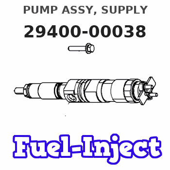
Information pump assy, supply
Rating:
Compare Prices: .
As an associate, we earn commssions on qualifying purchases through the links below

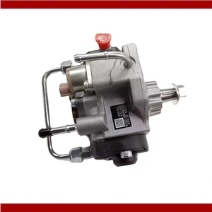
Fuel Injection Pump Compatible With 4HK1 Engine And ZX200-3 Excavator Model Numbers 294000-0037 294000-0038 294000-0039 8973060449
DEFYAN Model compatibility: Designed specifically for 4HK1 engine models, ensuring integration and reliable performance. || Usage range: Suitable for a variety of applications, particularly in ZX200-3 excavators, enhancing operational efficiency in heavy-duty tasks. || engineering: Manufactured with materials and strict production standards, delivering consistent fuel injection for engine performance. || Direct replacement: Functions as a direct replacement for part numbers 294000-0037, 294000-0038, 294000-0039, and 8973060449, simplifying installation and reducing downtime. || Reliability: Built to withstand demanding operating conditions, ensuring longevity and dependability in rugged environments. || Fuel efficiency: Designed to optimize fuel delivery, promoting better fuel economy and performance for your machinery. || Easier maintenance: Streamlined design facilitates straightforward maintenance, allowing for quick checks and adjustments to keep your excavator running smoothly.
DEFYAN Model compatibility: Designed specifically for 4HK1 engine models, ensuring integration and reliable performance. || Usage range: Suitable for a variety of applications, particularly in ZX200-3 excavators, enhancing operational efficiency in heavy-duty tasks. || engineering: Manufactured with materials and strict production standards, delivering consistent fuel injection for engine performance. || Direct replacement: Functions as a direct replacement for part numbers 294000-0037, 294000-0038, 294000-0039, and 8973060449, simplifying installation and reducing downtime. || Reliability: Built to withstand demanding operating conditions, ensuring longevity and dependability in rugged environments. || Fuel efficiency: Designed to optimize fuel delivery, promoting better fuel economy and performance for your machinery. || Easier maintenance: Streamlined design facilitates straightforward maintenance, allowing for quick checks and adjustments to keep your excavator running smoothly.

CR HP3 Fuel Injection Pump Compatible with Isuzu 4HK1 Engine 8-97306044-9 8-97306044-8 294000-0038
KoovDem Part Number: 294000-0038 8-97306044-8 8-97306044-9 || Engine Model: for Isuzu 4HK1 Engine || The HP3 Diesel Common Rail Injection Pump is a high-performance fuel delivery system for diesel engines, featuring advanced common rail technology for precise fuel injection. It improves engine performance, fuel efficiency, and reduces emissions. Built to withstand high pressure and harsh conditions, it is ideal for heavy-duty use in automotive, construction, and agricultural fields. Reliable and durable, it ensures consistent engine operation for optimal performance and reliability. || Friendly reminder: Before proceeding to replace the fuel pump, make sure it is compatible with the one you are looking to replace. If you are unsure about the compatibility, feel free to provide us with your model number for further assistance. || Service: We offer a 5-month warranty and around-the-clock support for customer service. If you have any questions about the product, please don't hesitate to contact us via email.
KoovDem Part Number: 294000-0038 8-97306044-8 8-97306044-9 || Engine Model: for Isuzu 4HK1 Engine || The HP3 Diesel Common Rail Injection Pump is a high-performance fuel delivery system for diesel engines, featuring advanced common rail technology for precise fuel injection. It improves engine performance, fuel efficiency, and reduces emissions. Built to withstand high pressure and harsh conditions, it is ideal for heavy-duty use in automotive, construction, and agricultural fields. Reliable and durable, it ensures consistent engine operation for optimal performance and reliability. || Friendly reminder: Before proceeding to replace the fuel pump, make sure it is compatible with the one you are looking to replace. If you are unsure about the compatibility, feel free to provide us with your model number for further assistance. || Service: We offer a 5-month warranty and around-the-clock support for customer service. If you have any questions about the product, please don't hesitate to contact us via email.

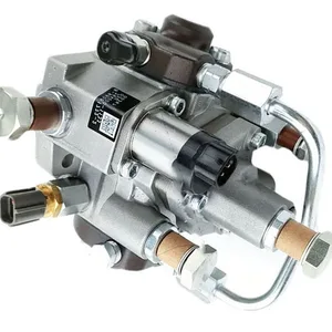
Fuel Injection Pump 294000-0038 8-97306044-0 294000-0031 Fits Compatible with Isuzu Engine 4HK1 4HK1-TCC 4HK1-TCS 5.2L
KoovDem Part Number: 294000-0038 8-97306044-0 294000-0031 Note: Please check the fitment carefully before purchase. Or just tell us the part number you need. || Part Name: Fuel Injection Pump || The 4HK1 engine is a reliable and efficient diesel engine commonly used in commercial trucks, generators, and construction equipment. It delivers powerful output while maintaining fuel efficiency, making it popular for heavy-duty applications. With advanced technology and precision engineering, it ensures superior reliability and longevity for long-haul transportation and demanding construction projects in various industries. || Compatible with Hitachi excavator models ZX200-3, ZX210-3, and ZX240-3. || Suitable for Isuzu engine models 4HK1, 4HK1-TCC, and 4HK1-TCS with a displacement of 5.2L.
KoovDem Part Number: 294000-0038 8-97306044-0 294000-0031 Note: Please check the fitment carefully before purchase. Or just tell us the part number you need. || Part Name: Fuel Injection Pump || The 4HK1 engine is a reliable and efficient diesel engine commonly used in commercial trucks, generators, and construction equipment. It delivers powerful output while maintaining fuel efficiency, making it popular for heavy-duty applications. With advanced technology and precision engineering, it ensures superior reliability and longevity for long-haul transportation and demanding construction projects in various industries. || Compatible with Hitachi excavator models ZX200-3, ZX210-3, and ZX240-3. || Suitable for Isuzu engine models 4HK1, 4HK1-TCC, and 4HK1-TCS with a displacement of 5.2L.
You can express buy:
USD 382.9
29-05-2025
29-05-2025
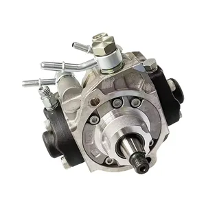
New HP3 Common Rail Diesel Engine 4HK1 Fuel Injection Pump Assy 8-97603044-8 8-97306044-9 294000-0038 294000-0039
USD 420.5
19-05-2025
19-05-2025
HP3 Common Rail Diesel Engine 4HK1 Fuel Injection Pump Assy 294000-0038 294000-0039 For ISUZU 8-97603044-8 8-97306044-9
USD 396.19
19-05-2025
19-05-2025
New HP3 Common Rail Diesel Engine 4HK1 Fuel Injection Pump Assy 8-97603044-8 8-97306044-9 294000-0038 294000-0039
Images:
USD 825.84

[19-May-2025]
USD 628.52

[13-May-2025]
USD 571.43

[02-May-2025]
USD 384.18

[19-May-2025]
Components :
| 001. | PUMP ASSY, SUPPLY | 29400-00038 |
| 001. | PUMP ASSY, SUPPLY | 29400-00038 |
| 001. | PUMP ASSY, SUPPLY | 29400-00038 |
| 001. | PUMP ASSY, SUPPLY | 29400-00038 |
| 001. | PUMP ASSY, SUPPLY | 29400-00038 |
| 001. | PUMP ASSY, SUPPLY | 29400-00038 |
| 001. | PUMP ASSY, SUPPLY | 29400-00038 |
| 001. | PUMP ASSY, SUPPLY | 29400-00038 |
| 001. | PUMP ASSY, SUPPLY | 29400-00038 |
| 002. | OVERHAUL KIT, SUPP | 29400-90031 |
Scheme ###:

| 000. | [01] | 29400-00032 | PUMP ASSY, SUPPLY | |
| 000. | [01] | 29400-00039 | PUMP ASSY, SUPPLY | |
| 000. | [01] | 29400-00038 | PUMP ASSY, SUPPLY | |
| 000. | [01] | 29400-00037 | PUMP ASSY, SUPPLY | |
| 000. | [01] | 29400-00036 | PUMP ASSY, SUPPLY | |
| 000. | [01] | 29400-00035 | PUMP ASSY, SUPPLY | |
| 000. | [01] | 29400-00034 | PUMP ASSY, SUPPLY | |
| 000. | [01] | 29400-00033 | PUMP ASSY, SUPPLY | |
| 001. | [01] | 29410-00063 | HOUSING SUB-ASSY, | |
| 002. | [02] | 29417-80010 | WASHER, CAMSHAFT | |
| 002. | [02] | 29417-80040 | WASHER, CAMSHAFT | |
| 003. | [01] | 29419-10010 | CAMSHAFT, SUPPLY P | |
| 004. | [01] | 29402-10010 | KEY, WOODRUFF | |
| 004. | [01] | 29402-10020 | KEY, WOODRUFF | S2289-11200-A |
| 005. | [01] | 29417-00010 | RING SUB-ASSY, CAM | |
| 005. | [01] | 29417-00120 | RING SUB-ASSY, CAM | |
| 006. | [01] | 29412-00310 | COVER SUB-ASSY, BE | |
| 006. | [01] | 29412-00270 | COVER SUB-ASSY, BE | |
| 006. | [01] | 29412-00021 | COVER SUB-ASSY, BE | |
| 006-001. | [01] | 29419-70010 | SEAL, OIL | |
| 007. | [06] | 09644-90110 | BOLT, SOCKET | 23371-E0010 |
| 008. | [01] | 29419-80050 | O-RING, SUPPLY PUM | |
| 009. | [02] | 29419-80030 | O-RING, SUPPLY PUM | |
| 010. | [01] | 29418-30040 | PLATE, FEED PUMP, | |
| 010. | [01] | 29418-30170 | PLATE, FEED PUMP, | |
| 011. | [01] | 29418-40031 | COVER, FEED PUMP | |
| 011. | [01] | 29418-40140 | COVER, FEED PUMP | |
| 012. | [01] | 29418-70040 | KEY, FEED PUMP | |
| 012. | [01] | 29418-70010 | KEY, FEED PUMP | |
| 013. | [01] | 29418-00010 | ROTOR SET, FEED PU | |
| 013. | [01] | 29418-00080 | ROTOR SET, FEED PU | |
| 014. | [05] | 09644-90050 | BOLT, SOCKET | S2273-31010-A |
| 015. | [01] | 29409-00860 | ELEMENT KIT, SUPPL | |
| 015. | [01] | 29409-00370 | ELEMENT KIT, SUPPL | |
| 015. | [01] | 29409-00190 | ELEMENT KIT, SUPPL | |
| 015. | [01] | 29409-00030 | ELEMENT KIT, SUPPL | |
| 016. | [01] | 29409-00780 | ELEMENT KIT, SUPPL | |
| 016. | [01] | 29409-00300 | ELEMENT KIT, SUPPL | |
| 016. | [01] | 29409-00110 | ELEMENT KIT, SUPPL | |
| 016. | [01] | 29409-00040 | ELEMENT KIT, SUPPL | |
| 017. | [02] | 29415-90010 | SPRING, PLUNGER | |
| 017. | [02] | 29415-90040 | SPRING, PLUNGER | |
| 018. | [02] | 29419-80010 | O-RING, SUPPLY PUM | |
| 019. | [02] | 29419-80040 | O-RING, SUPPLY PUM | |
| 020. | [06] | 29419-90010 | BOLT, SOCKET | |
| 021. | [02] | 29414-00082 | VALVE SUB-ASSY, SU | |
| 021. | [02] | 29414-00150 | VALVE SUB-ASSY, SU | |
| 022. | [02] | 29419-80020 | O-RING, SUPPLY PUM | |
| 023. | [02] | 29413-50010 | PLUG, CYLINDER | |
| 029. | [01] | 09806-60030 | O-RING, DISTRIBUTI | |
| 030. | [01] | 17973-00100 | SENSOR, FUEL TEMPE | |
| 030. | [01] | 17973-00020 | SENSOR, FUEL TEMPE | |
| 031. | [01] | 29420-00020 | VALVE ASSY, SUCTIO | |
| 031. | [01] | 29420-00050 | VALVE ASSY, SUCTIO | |
| 031. | [01] | 29420-00650 | VALVE ASSY, SUCTIO | |
| 031-001. | [01] | 29428-60010 | O-RING, VALVE | |
| 032. | [01] | 29428-50010 | O-RING, SOLENOID | |
| 033. | [01] | 29416-00011 | VALVE SUB-ASSY, RE | |
| 033. | [01] | 29416-00130 | VALVE SUB-ASSY, RE | |
| 033-001. | [01] | 29419-80060 | O-RING, SUPPLY PUM | |
| 033-002. | [01] | 29419-80070 | O-RING, SUPPLY PUM | |
| 034. | [01] | 29401-00200 | PIPE, SUPPLY PUMP | |
| 034. | [01] | 29401-00120 | PIPE, SUPPLY PUMP | |
| 034. | [01] | 29401-00020 | PIPE, SUPPLY PUMP | |
| 035. | [02] | 29416-90010 | PIN, STOPPER | |
| 036. | [01] | 29411-50010 | PLUG, FILTER | |
| 037. | [01] | 29411-70010 | GASKET, PLUG | |
| 038. | [01] | 09543-80010 | SCREW, HOLLOW | |
| 038. | [01] | 09543-80170 | SCREW, HOLLOW | |
| 039. | [02] | 94901-02530 | WASHER | S2284-72310-A |
| 040. | [01] | 94919-80260 | COLLAR, PRESSBOARD | S2233-21650-A |
| 041. | [01] | 94918-00310 | SCREW, HOLLOW | S2283-51310-A |
| 042. | [02] | 94901-02490 | WASHER | S2287-71100-A |
| 043. | [01] | 94919-80270 | COLLAR, PRESSBOARD | S2284-32240-A |
| 044. | [01] | 94905-62390 | NUT | S2282-52570-A |
| 045. | [01] | 09737-00010 | FILTER SUB-ASSY | |
| 046. | [01] | 09604-90460 | O-RING | |
| 052. | [01] | 09001-40160 | CAP, VALVE HOLDER | |
| 101. | [01] | 29400-90010 | OVERHAUL KIT, SUPP | |
| 102. | [01] | 29400-90020 | OVERHAUL KIT, SUPP | |
| 102. | [01] | 29400-90100 | OVERHAUL KIT, SUPP | |
| 200. | [01] | 29400-90040 | OVERHAUL KIT, SUPP | |
| 200. | [01] | 29400-90031 | OVERHAUL KIT, SUPP | |
| 201. | [02] | 29400-90940 | OVERHAUL KIT, SUPP | |
| 201. | [02] | 29400-90370 | OVERHAUL KIT, SUPP | |
| 300. | [01] | 29409-05000 | ELEMENT KIT, SUPPL | |
| 301. | [01] | 29409-05010 | ELEMENT KIT, SUPPL | |
| 302. | [01] | 29413-10220 | HOLDER, DELIVERY V |
Include in #3:
Cross reference number
| Part num | Firm num | Firm | Name |
| 29400-00038 | 1670089T0C | PUMP ASSY, SUPPLY |
Information:
2. Disconnect the fuel injection lines (2) from pump housing. Put plugs or caps in all lines and openings.3. Remove the three bolts that hold the fuel filter (3) to the aftercooler housing.4. Disconnect the sensing line (1) for the fuel ratio control from the aftercooler housing. 5. Disconnect the oil supply line (4) from the turbocharger.6. Remove the two water lines (5). 7. Disconnect the water outlet line (6) for the air compressor from the cylinder head.8. Remove the bolts (7) that fasten the cylinder head to the cylinder block. 9. Install 3/8"-16NC forged eyebolts in the cylinder head. Fasten a hoist and remove the cylinder head assembly. Weight of cylinder head assembly is 575 lb. (260 kg). Be sure to install a new gasket between the spacer plate and the cylinder block before installing the cylinder head assembly. See REMOVE and INSTALL SPACER PLATE in DISASSEMBLY AND ASSEMBLY.Install Cylinder Head Assembly
1. Clean the top surface of spacer plate and the surface it is in contact with on the cylinder head.2. Install the cylinder head gasket, water seals, and gasket on timing gear cover. 3. Install the 3/8"-16NC forged eyebolts in the cylinder head. Fasten a hoist and put the cylinder head assembly into position on the engine. Make sure the gear (1) in cylinder head is engaged with drive gear (2). 4. Put 9M3710 Anti-Seize Compound on the threads of the bolts for cylinder head. Install the bolts and washers. Tighten the bolts as follows: 1 -Tighten all bolts in number order to 135 lb.ft. (18.7 mkg).2 -Tighten all bolts in number order to 185 5 lb.ft. (25.6 0.7 mkg).3 -Tighten all bolts using hand torque only to 185 5 lb.ft. (25.6 0.7 mkg). 5. Install the two water lines (4).6. Connect the oil supply line (3) to the turbocharger.7. Connect the water outlet line (5) for the air compressor to the cylinder head. 8. Connect the sensing line (6) for the fuel ratio control to the aftercooler housing.9. Put the fuel filter in position, and install the three bolts.10. Remove the plugs and fuel injection lines and pumps. Connect the fuel injection lines (7) to the pumps. Tighten the nuts on fuel lines to 30 5 lb.ft. (4.1 0.7 mkg).11. Fill the cooling system with coolant.end by: a) install camshaft housingb) install fan drive
1. Clean the top surface of spacer plate and the surface it is in contact with on the cylinder head.2. Install the cylinder head gasket, water seals, and gasket on timing gear cover. 3. Install the 3/8"-16NC forged eyebolts in the cylinder head. Fasten a hoist and put the cylinder head assembly into position on the engine. Make sure the gear (1) in cylinder head is engaged with drive gear (2). 4. Put 9M3710 Anti-Seize Compound on the threads of the bolts for cylinder head. Install the bolts and washers. Tighten the bolts as follows: 1 -Tighten all bolts in number order to 135 lb.ft. (18.7 mkg).2 -Tighten all bolts in number order to 185 5 lb.ft. (25.6 0.7 mkg).3 -Tighten all bolts using hand torque only to 185 5 lb.ft. (25.6 0.7 mkg). 5. Install the two water lines (4).6. Connect the oil supply line (3) to the turbocharger.7. Connect the water outlet line (5) for the air compressor to the cylinder head. 8. Connect the sensing line (6) for the fuel ratio control to the aftercooler housing.9. Put the fuel filter in position, and install the three bolts.10. Remove the plugs and fuel injection lines and pumps. Connect the fuel injection lines (7) to the pumps. Tighten the nuts on fuel lines to 30 5 lb.ft. (4.1 0.7 mkg).11. Fill the cooling system with coolant.end by: a) install camshaft housingb) install fan drive