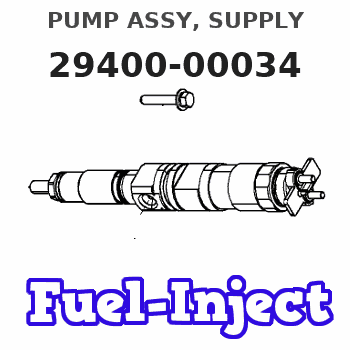
Information pump assy, supply
Rating:
Compare Prices: .
As an associate, we earn commssions on qualifying purchases through the links below

294000-0034 8-97306044-9 294000-2600 294000-0039 8-98346317-0 CR HP3 Fuel Injection Pump Suitable for Isuzu 4HK1 5.2L Engine Hitachi ZX200-3 ZX210-3 ZX240-3 Excavator
OfkZynodor Part Name:Diesel Fuel Injection Pump || Part Number:294000-2600 294000-0034 8-98346317-0 294000-0039 8-97306044-9 8-97306044-4 || Application:Suitable for Isuzu 4HK1 5.2L Engine Hitachi ZX200-3 ZX210-3 ZX240-3 Excavator || Please make sure to carefully compare the photos and check the part numbers before making the purchase. If you are unable to confirm your engine model or part number, please leave us a message and we will assist you in confirming that the product you purchase is the one you need. || Your order is not merely a single purchase but the beginning of a cooperative journey, aiming to ensure the safe and smooth operation of your vehicle. We are proud to offer you reliable precision engineering components and unparalleled services.
OfkZynodor Part Name:Diesel Fuel Injection Pump || Part Number:294000-2600 294000-0034 8-98346317-0 294000-0039 8-97306044-9 8-97306044-4 || Application:Suitable for Isuzu 4HK1 5.2L Engine Hitachi ZX200-3 ZX210-3 ZX240-3 Excavator || Please make sure to carefully compare the photos and check the part numbers before making the purchase. If you are unable to confirm your engine model or part number, please leave us a message and we will assist you in confirming that the product you purchase is the one you need. || Your order is not merely a single purchase but the beginning of a cooperative journey, aiming to ensure the safe and smooth operation of your vehicle. We are proud to offer you reliable precision engineering components and unparalleled services.

CR HP3 Fuel Injection Pump Compatible with Isuzu 4HK1 4HJ1 5.2L Engine F-Series N-Series Trucks 8973060444 8-97306044-4 294000-0034
KoovDem Part Number: 294000-0034 8-97306044-4 8973060444 || Vehicle Application:For Isuzu Trucks FRR FSR FTR FVR FSS NPR NQR NRR || for verification. This will help ensure that you receive the correct part for your vehicle. It is important to double check the accuracy of the part numbers to avoid any delays or inconvenience. Thank you for your attention to detail and for choosing our services. || Service: We offer a 5-month warranty on all products, along with 24-hour customer support for any inquiries or issues. If you have any questions regarding the product, please don't hesitate to reach out to us via email.
KoovDem Part Number: 294000-0034 8-97306044-4 8973060444 || Vehicle Application:For Isuzu Trucks FRR FSR FTR FVR FSS NPR NQR NRR || for verification. This will help ensure that you receive the correct part for your vehicle. It is important to double check the accuracy of the part numbers to avoid any delays or inconvenience. Thank you for your attention to detail and for choosing our services. || Service: We offer a 5-month warranty on all products, along with 24-hour customer support for any inquiries or issues. If you have any questions regarding the product, please don't hesitate to reach out to us via email.

CR HP3 Fuel Injection Pump Compatible with Isuzu 4HK1 5.2L Engine N-Series Trucks 294000-0039 294000-0034 8-97306044-4 8-97306044-9
KoovDem Part Number: 294000-0039 294000-0034 8-97306044-4 8-97306044-9 || Engine Model: for Isuzu 4HK1 Engine 5.2L || The HP3 Common Rail Diesel Pump is a crucial component in a vehicle's fuel system, delivering high-pressure fuel to the engine's injectors for optimal combustion efficiency. Known for its reliability and efficiency, this pump is commonly used in diesel vehicles. Regular maintenance is important to ensure smooth operation and prevent issues. This pump plays a vital role in the vehicle's performance and is a popular choice for many manufacturers. || for verification. This will help ensure that you receive the correct part for your vehicle. It is important to double check the accuracy of the part numbers to avoid any delays or inconvenience. Thank you for your attention to detail and for choosing our services. || Service: We offer a 5-month warranty on all products, along with 24-hour customer support for any inquiries or issues. If you have any questions regarding the product, please don't hesitate to reach out to us via email.
KoovDem Part Number: 294000-0039 294000-0034 8-97306044-4 8-97306044-9 || Engine Model: for Isuzu 4HK1 Engine 5.2L || The HP3 Common Rail Diesel Pump is a crucial component in a vehicle's fuel system, delivering high-pressure fuel to the engine's injectors for optimal combustion efficiency. Known for its reliability and efficiency, this pump is commonly used in diesel vehicles. Regular maintenance is important to ensure smooth operation and prevent issues. This pump plays a vital role in the vehicle's performance and is a popular choice for many manufacturers. || for verification. This will help ensure that you receive the correct part for your vehicle. It is important to double check the accuracy of the part numbers to avoid any delays or inconvenience. Thank you for your attention to detail and for choosing our services. || Service: We offer a 5-month warranty on all products, along with 24-hour customer support for any inquiries or issues. If you have any questions regarding the product, please don't hesitate to reach out to us via email.
Include in #3:

Cross reference number
| Part num | Firm num | Firm | Name |
| 29400-00034 | PUMP ASSY, SUPPLY |
Information:
start by: a) separation of governor from fuel injection pump housing1. Remove the cover (16) from rack centering pin. Move the rack to the fuel "OFF" position, and push in on the centering pin (15). Install the cover (16) as shown to keep the centering pin in position during disassembly and assembly of injection pump housing. 2. Move the rack toward the fuel "ON" position until the slot in rack (13) is against the rack centering pin (15). The rack is now in the "CENTER" position.
Do not try to remove the fuel injection pumps if the rack is not in "CENTER" position.
3. Remove the fuel injection pumps as follows: a) Remove the caps and felt washer (1).b) Install wrench (A), and remove the bushing (2) from housing. c) Install extractor (B).d) Remove the bushing (2) and wrench (A).e) Remove the seal (3).f) Lift the fuel injection pump up and out of housing.g) Remove the spacer (9). Keep the spacer (9) together with its respective fuel injection pump. Put identification on the pumps and spacers as to their location in the pump housing.4. Disassemble the fuel injection pumps as follows: a) Remove the ring (7), bonnet (4), check valve (6), and spring (5) from barrel (8).b) Remove the plunger assembly (11), washer (12), and spring (10) from barrel (8).
Be very careful when disassembling and assembling the fuel injection pumps to prevent damage to the plunger surfaces. The barrel and plunger assemblies are fitted together, and must not be used with other barrels or plunger assemblies.
5. Remove the rack centering pin, spring, and cover. 6. Remove the rack (13), and lifters (14). Put identification on the lifters as to their location in the pump housing. Keep the lifters with their respective pumps and spacers. 7. Remove the bolt, lock, and plate (17) from the camshaft. Remove the spring and gear assembly (18).8. Remove the camshaft (20) from pump housing.9. Remove the rack bearings (19) from housing. 10. Use tool setup (C) to remove the camshaft bearings from the fuel injection pump housing.Assemble Fuel Injection Pump Housing
1. Use tool group (D) to install the rack bearing in the accessory drive housing end of injection pump housing.2. Install the rack bearing in governor end of housing using tool setup (E). The bearing must be installed .195 .005 in. (4.95 0.13 mm) below outside face of pump housing.3. Use tool group (C) to install the camshaft bearings in housing. Make sure the oil holes in bearings are in alignment with oil holes in pump housing. 4. Put clean engine oil on the camshaft bearings. Install the camshaft (1) in pump housing. 5. Install the gear (3), spring, plate, lock, and bolt (2) on the camshaft.6. Put clean engine oil on lobes of camshaft. 7. Install the lifters (4) in their respective positions in pump housing. Install the spacers in their correct locations in housing. If new lifters are to be installed, it will be necessary to check the timing