Information pump assy, injecti
Nozzle:
0935006520
Rating:
KIT List:
| Pump assy, injecti | 0960100551 |
Components :
| 001. | PUMP ASSY, INJECTI | 19600-03480 |
| 002. | BELLOWS ASSY, PNEU | 09071-00620 |
| 003. | COVER SUB-ASSY, GO | 09644-01690 |
| 004. | RING SUB-ASSY, ROL | 09618-00050 |
| 005. | COVER SUB-ASSY, TI | 09621-01060 |
| 006. | GOVERNOR ASSY, TOR | 09627-01460 |
| 007. | SHIM, PLUNGER ADJU | 09640-60020 |
Scheme ###:
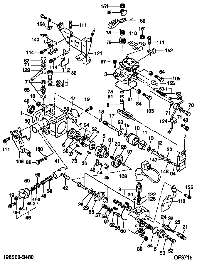
| 000. | [01] | 19600-03480 | PUMP ASSY, INJECTI | R2P1 13 800B |
| 001. | [01] | 09611-00881 | HOUSING SUB-ASSY, | |
| 002. | [01] | 09640-01710 | HEAD SUB-ASSY, DIS | |
| 003. | [01] | 09071-00620 | BELLOWS ASSY, PNEU | |
| 004. | [01] | 09612-10150 | SHAFT, DRIVE | |
| 005. | [01] | 09618-00050 | RING SUB-ASSY, ROL | S503 24 040 |
| 006. | [01] | 09614-00030 | PUMP SUB-ASSY, FUE | RF10 24 020 |
| 007. | [01] | 09627-01460 | GOVERNOR ASSY, TOR | |
| 008. | [01] | 09646-01920 | SHAFT SUB-ASSY, SP | |
| 009. | [01] | 09603-00520 | SOLENOID ASSY, FUE | S5A1 13 VF4 |
| 009-001. | [01] | 09604-90350 | O-RING | S5A1 13 VJ7 |
| 010. | [01] | 09626-00050 | HOLDER SUB-ASSY, F | S501 24 231 |
| 011. | [04] | 09626-30030 | FLYWEIGHT, DISTRIB | S501 24 232 |
| 012. | [01] | 09625-20230 | SLEEVE, GOVERNOR | |
| 013. | [01] | 09626-50030 | WASHER, FLYWEIGHT | S501 24 233 |
| 015. | [01] | 09626-50020 | WASHER, FLYWEIGHT | S501 24 229 |
| 016. | [01] | 09625-40050 | NUT, GOVERNOR SHAF | S501 24 221 |
| 017. | [01] | 09625-10020 | SHAFT, GOVERNOR MA | S501 24 222 |
| 018. | [01] | 94914-02930 | O-RING | S501 24 223 |
| 019. | [04] | 09644-90110 | BOLT, SOCKET | S5A1 13 TD4 |
| 020. | [01] | 09625-50020 | RING, GOVERNOR SLE | RF10 24 130 |
| 021. | [04] | 09643-00180 | VALVE SUB-ASSY, SN | RF1L 13 V23 |
| 022. | [04] | 09642-00510 | VALVE SUB-ASSY, DI | 4782 13 V21B |
| 023. | [04] | 09642-70010 | SPRING, DELIVERY V | S501 24 142 |
| 024. | [04] | 09642-60070 | GASKET, DELIVERY V | S5A1 13 V81 |
| 026. | [01] | 09623-00250 | CAMPLATE SUB-ASSY, | |
| 028. | [01] | 09624-50020 | PLATE, PLUNGER, LW | S501 24 071 |
| 029. | [01] | 09624-40040 | PLATE, PLUNGER, UP | S501 24 072 |
| 030. | [01] | 09622-40040 | SPRING, COUPLING | S501 24 048 |
| 031. | [01] | 09622-20020 | COUPLING | S501 24 047 |
| 032. | [01] | 09612-40030 | GEAR, GOVERNOR DRI | S501 24 035 |
| 033. | [02] | 09612-60020 | JOINT, RUBBER | S501 24 034 |
| 034. | [01] | 09612-50010 | WASHER, DRIVE SHAF | S501 24 036 |
| 035. | [01] | 09614-70052 | COVER, FEED PUMP | VS01 13 VF1 |
| 036. | [01] | 94913-00260 | KEY, WOODRUFF | S501 24 032 |
| 037. | [01] | 94913-00300 | KEY, WOODRUFF | |
| 038. | [01] | 09620-82400 | SPRING, TIMER, OUT | |
| 040. | [01] | 09603-90040 | SEAL, 0IL | |
| 041. | [01] | 09619-01310 | PISTON ASSY, TIMER | |
| 042. | [01] | 09621-30020 | SUB-PISTON, TIMER | S501 24 053 |
| 043. | [01] | 09620-50020 | PIN, TIMER SLIDE | S501 24 044 |
| 044. | [01] | 09621-60120 | STOPPER, TIMER SLI | S501 24 045 |
| 045. | [01] | 09621-10080 | CLIP, TIMER | S501 24 046 |
| 046. | [01] | 09621-00870 | COVER SUB-ASSY, TI | |
| 046-001. | [01] | 09621-80870 | COVER, TIMER | |
| 046-002. | [01] | 09621-60110 | STOPPER, TIMER SLI | |
| 046-003. | [01] | 09604-90290 | O-RING | |
| 046-004. | [01] | 94905-05010 | NUT, HEXAGON | |
| 047. | [01] | 09621-80270 | COVER, TIMER | VS01 13 TA5 |
| 048. | [1C] | 09620-82290 | SPRING, TIMER, OUT | |
| 048. | [1C] | 09620-81980 | SPRING, TIMER, OUT | |
| 048. | [1C] | 09620-81970 | SPRING, TIMER, OUT | |
| 048. | [1C] | 09620-81930 | SPRING, TIMER, OUT | |
| 048. | [1C] | 09620-81540 | SPRING, TIMER, OUT | |
| 049. | [01] | 09644-90260 | BOLT, SOCKET | VS01 13 V53 |
| 050. | [03] | 09604-90400 | O-RING | S501 24 051 |
| 051. | [01] | 09641-70040 | PLUG, DISTRIBUTIVE | S501 24 151 |
| 052. | [01] | 09641-80020 | BOLT, DISTRIBUTIVE | S501 24 152 |
| 053. | [01] | 09642-60030 | GASKET, DELIVERY V | |
| 054. | [01] | 09604-90510 | O-RING | S501 24 153 |
| 055. | [01] | 09624-70010 | SHEET, PLUNGER SPR | S501 24 073 |
| 056. | [02] | 09623-70010 | GUIDE SUB-ASSY, PL | S501 24 076 |
| 057. | [02] | 09623-60040 | SPRING, PLUNGER | RF10 24 074 |
| 058. | [02] | 09624-60010 | SHEET, PLUNGER SPR | S501 24 075 |
| 060. | [01] | 94914-02980 | O-RING | S501 24 105 |
| 062. | [02] | 09627-90010 | SPRING, LEVER SUPP | S501 24 078 |
| 063. | [01] | 09648-00010 | SMOKE SET SUB-ASSY | VS01 13 VM2 |
| 063-001. | [01] | 09604-90470 | O-RING | S501 24 196 |
| 064. | [01] | 90166-06051 | NUT, HEXAGON | S501 24 176 |
| 066. | [01] | 09621-40180 | WASHER, TIMER SENS | |
| 067. | [04] | 09644-90020 | BOLT, SOCKET | S501 24 163 |
| 068. | [01] | 09644-50140 | GUIDE, RETURN SPRI | |
| 070. | [01] | 09602-00030 | SCREW SUB-ASSY, OV | S501 24 280 |
| 071. | [05] | 09024-10010 | WASHER, AIR BLEEDE | S501 24 283 |
| 073. | [02] | 94900-20420 | SCREW, COUNTERSUNK | S501 24 024 |
| 075. | [01] | 09604-90300 | O-RING | S501 24 171 |
| 078. | [01] | 09644-41280 | SPRING, RETURN | |
| 079. | [01] | 09644-41290 | SPRING, RETURN | |
| 080. | [1C] | 09643-66420 | LEVER, ADJUSTING | |
| 080. | [1C] | 09643-66430 | LEVER, ADJUSTING | |
| 080. | [1C] | 09643-66440 | LEVER, ADJUSTING | |
| 081. | [01] | 09644-60100 | GASKET, GOVERNOR C | S501 24 162 |
| 082. | [01] | 09616-00280 | VALVE SUB-ASSY, RE | |
| 082-001. | [01] | 09604-90180 | O-RING | S501 24 271 |
| 082-002. | [01] | 09604-90500 | O-RING | S501 24 272 |
| 084. | [01] | 09634-20010 | NUT, LOCK | S501 24 182 |
| 085. | [01] | 94918-00770 | SCREW, HOLLOW | RF66 13 VG7 |
| 086. | [02] | 09626-90020 | BOLT, GOVERNOR LIN | S501 24 201 |
| 087. | [01] | 94905-50300 | NUT, CAP | RF66 13 VX7 |
| 088. | [04] | 09644-90070 | BOLT, SOCKET | |
| 091. | [01] | 09627-30140 | WASHER, GOVERNOR T | |
| 092. | [2C] | 09624-80220 | SHIM, PLUNGER SPRI | |
| 092. | [2C] | 09624-80110 | SHIM, PLUNGER SPRI | S501 24 092 |
| 092. | [2C] | 09624-80100 | SHIM, PLUNGER SPRI | S501 24 091 |
| 092. | [2C] | 09624-80090 | SHIM, PLUNGER SPRI | S501 24 089 |
| 092. | [2C] | 09624-80080 | SHIM, PLUNGER SPRI | S501 24 088 |
| 092. | [2C] | 09624-80070 | SHIM, PLUNGER SPRI | S501 24 087 |
| 092. | [2C] | 09624-80060 | SHIM, PLUNGER SPRI | S501 24 086 |
| 092. | [2C] | 09624-80050 | SHIM, PLUNGER SPRI | S501 24 085 |
| 092. | [2C] | 09624-80040 | SHIM, PLUNGER SPRI | S501 24 084 |
| 092. | [2C] | 09624-80030 | SHIM, PLUNGER SPRI | S501 24 083 |
| 092. | [2C] | 09624-80020 | SHIM, PLUNGER SPRI | S501 24 082 |
| 092. | [2C] | 09624-80010 | SHIM, PLUNGER SPRI | S501 24 081 |
| 093. | [1C] | 09626-60280 | WASHER, GOVERNOR G | |
| 093. | [1C] | 09626-60290 | WASHER, GOVERNOR G | |
| 093. | [1C] | 09626-60300 | WASHER, GOVERNOR G | |
| 093. | [1C] | 09626-60310 | WASHER, GOVERNOR G | |
| 093. | [1C] | 09626-60320 | WASHER, GOVERNOR G | |
| 093. | [1C] | 09626-60330 | WASHER, GOVERNOR G | |
| 093. | [1C] | 09626-60340 | WASHER, GOVERNOR G | |
| 093. | [1C] | 09626-60270 | WASHER, GOVERNOR G | |
| 093. | [1C] | 09626-60180 | WASHER, GOVERNOR G | |
| 093. | [1C] | 09626-60170 | WASHER, GOVERNOR G | RF10 24 129 |
| 093. | [1C] | 09626-60100 | WASHER, GOVERNOR G | S501 24 224 |
| 093. | [1C] | 09626-60110 | WASHER, GOVERNOR G | S501 24 225 |
| 093. | [1C] | 09626-60120 | WASHER, GOVERNOR G | S501 24 226 |
| 093. | [1C] | 09626-60130 | WASHER, GOVERNOR G | S501 24 227 |
| 093. | [1C] | 09626-60140 | WASHER, GOVERNOR G | S501 24 228 |
| 093. | [1C] | 09626-60150 | WASHER, GOVERNOR G | S501 24 248 |
| 093. | [1C] | 09626-60160 | WASHER, GOVERNOR G | S501 24 249 |
| 094. | [1C] | 09625-60600 | PLUG, GOVERNOR SLE | RF10 24 632 |
| 094. | [1C] | 09625-60590 | PLUG, GOVERNOR SLE | RF10 24 631 |
| 094. | [1C] | 09625-60580 | PLUG, GOVERNOR SLE | RF10 24 630 |
| 094. | [1C] | 09625-60570 | PLUG, GOVERNOR SLE | RF10 24 629 |
| 094. | [1C] | 09625-60560 | PLUG, GOVERNOR SLE | RF10 24 628 |
| 094. | [1C] | 09625-60550 | PLUG, GOVERNOR SLE | RF10 24 627 |
| 094. | [1C] | 09625-60540 | PLUG, GOVERNOR SLE | |
| 094. | [1C] | 09625-60530 | PLUG, GOVERNOR SLE | |
| 094. | [1C] | 09625-60520 | PLUG, GOVERNOR SLE | |
| 094. | [1C] | 09625-60510 | PLUG, GOVERNOR SLE | |
| 094. | [1C] | 09625-60500 | PLUG, GOVERNOR SLE | |
| 094. | [1C] | 09625-60490 | PLUG, GOVERNOR SLE | |
| 094. | [1C] | 09625-60480 | PLUG, GOVERNOR SLE | |
| 096. | [01] | 09644-80111 | COLLAR, SMOKE SET | S501 24 197 |
| 097. | [1C] | 09640-60520 | SHIM, PLUNGER ADJU | S501 24 122 |
| 097. | [1C] | 09640-60420 | SHIM, PLUNGER ADJU | S501 24 119 |
| 097. | [1C] | 09640-60270 | SHIM, PLUNGER ADJU | S501 24 116 |
| 097. | [1C] | 09640-60170 | SHIM, PLUNGER ADJU | S501 24 114 |
| 097. | [1C] | 09640-60020 | SHIM, PLUNGER ADJU | S501 24 111 |
| 105. | [02] | 94904-50210 | BOLT, HEXAGON, W/ | |
| 108. | [01] | 09604-51040 | WIRE SUB-ASSY | R2L3 13 VZ9 |
| 109. | [01] | 09621-01060 | COVER SUB-ASSY, TI | |
| 110. | [01] | 09643-83670 | BRACKET, IDLE UP | |
| 111. | [06] | 09644-90130 | BOLT, SOCKET | RFP1 13 VV1 |
| 112. | [01] | 09643-82870 | BRACKET, IDLE UP | RFP1 13 TN2 |
| 114. | [04] | 09644-90100 | BOLT, SOCKET | VS01 13 TP3 |
| 116. | [01] | 09643-83501 | BRACKET, IDLE UP | R2L3 13 VW1 |
| 121. | [01] | 09647-11050 | BRACKET SUB-ASSY, | |
| 122. | [01] | 09653-00071 | FILTER, SUB-ASSY | S5A1 13 VF5 |
| 123. | [01] | 09221-80220 | NIPPLE SUB-ASSY, S | VS01 13 VH5 |
| 124. | [01] | 09221-80280 | NIPPLE SUB-ASSY, S | RFP1 13 VH6 |
| 126. | [01] | 09606-40110 | WASHER | S5A1 13 VK3 |
| 135. | [02] | 09644-90140 | BOLT, SOCKET | RF2A 13 TP3 |
| 140. | [01] | 09647-00520 | IDLE UP SUB-ASSY | RFP1 13 TR4 |
| 147. | [01] | 90577-02000 | E-RING | RF10 24 235 |
| 148. | [01] | 94910-02860 | BEARING, BALL | RF10 24 467 |
| 151. | [03] | 94905-61680 | NUT | S5A1 13 VY1 |
| 152. | [01] | 09602-90630 | CLIP, CONNECTOR SU | |
| 155. | [01] | 09646-80220 | CAP RUBBER | |
| 156. | [01] | 09266-40350 | SCREW, LEVER STOP | |
| 157. | [01] | 09634-20060 | NUT, LOCK | RFP1 13 VX7 |
| 160. | [02] | 09642-60130 | GASKET, DELIVERY V |
Include in #3:
19600-03480
as PUMP ASSY, INJECTI
Cross reference number
| Part num | Firm num | Firm | Name |
| 19600-03480 | R2P1 13 80 | PUMP ASSY, INJECTI | |
| R2P1 13 800B | MAZDA | PUMP ASSY, INJECTI |
Information:
6. Remove four bolts (7).7. Remove nuts (8) and one bolt (not shown). Remove water pump.Install Water Pump
1. Put the water pump in position on the timing gear cover. Install nuts (8) and one bolt that hold the pump to the timing gear cover.2. Install four bolts (7). 3. Put clean engine oil or glycerin on O-ring seals (9). Install elbow (3). 4. Put cover (2) in position on the water pump. Install bolts (4) that hold the cover to the water pump and bolts (5) that hold elbow (3) to the cover.5. Install elbow (1).6. Install line (6).7. Fill the cooling system to the proper level. See the Operation & Maintenance Manual.Disassemble Water Pump
Start By:a. remove water pump 1. Remove O-ring seal (1) from adapter (2).2. Remove adapter (2) with a screwdriver. Remove the seal from the edge of adapter (2).3. Remove bolt (3) and washer. 4. Remove impeller (4) from the water pump housing with Tooling (A). 5. Remove seal assembly (5). Remove ring and seal (6). 6. Remove the bolt and washer that hold gear (7) on the water pump shaft.7. Remove gear (7) with Tooling (B).8. Remove bolts and retainer (9).9. Remove O-ring seal (8). 10. Remove shaft (10) and bearings as a unit.11. Remove bearing (11), spacer (12) and bearing (13) from shaft (10).12. Remove lip-type seal from the gear side of the water pump. Remove ring and seal from the impeller side of the water pump.Assemble Water Pump
1. Put clean engine oil or glycerin on the lip of seal (1). Install seal (1) as shown with Tooling (A). 2. Install bearing (4), spacer (3) and bearing (5) on shaft (2). Install shaft (2) in the pump housing. 3. Install retainer (7) and O-ring seal (8).4. Install gear (6). Install washer and bolt that hold gear (6) to shaft (2).
Clean water only is permitted for use as a lubricant for assistance at installation. Do not damage or put hands on the wear surface of the carbon ring or the ceramic ring. Install the ceramic ring with the smoothest face of the ring toward the carbon seal assembly.
5. Put ceramic ring (10) in position in the rubber seal (9). Use hand pressure and Tool (11) (which is with the replacement ring) to install the ceramic ring in the housing. 6. Remove the spring from seal assembly (12). Use hand pressure and Tool (11) (which is with the replacement ring) to install the seal assembly. Push seal assembly on the shaft until the seal faces make light contact. 7. Install spring (13) on the seal assembly and impeller (14) on the shaft. Install the bolt and washer on the shaft. Tighten the bolt to a torque of 39 3 N m (29 2 lb ft). 8. Install O-ring seals (15) on adapter (16). Put clean engine oil on O-ring seals.9. Install adapter (16) in the pump housing. Make sure the notch in the adapter is in alignment with dowel (17).End By:a. install water pump