Information pump assy, injecti
Nozzle:
0935006020
Rating:
KIT List:
| Pump assy, injecti | 0960100561 |
Components :
| 001. | PUMP ASSY, INJECTI | 19600-00130 |
| 002. | RING SUB-ASSY, ROL | 09618-00050 |
| 003. | COVER SUB-ASSY, TI | 09621-01060 |
| 004. | GOVERNOR ASSY, TOR | 09627-00171 |
| 005. | SHIM, PLUNGER ADJU | 09640-60020 |
| 006. | COMPENSATOR SUB-AS | 09649-01350 |
| 007. | COVER SUB-ASSY, GO | 09644-01580 |
Scheme ###:
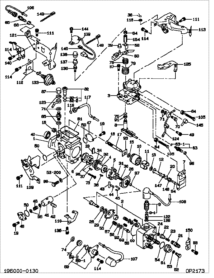
| 000. | [01] | 19600-00130 | PUMP ASSY, INJECTI | RFP2 13 800 |
| 001. | [01] | 09611-01100 | HOUSING SUB-ASSY, | |
| 002. | [01] | 09640-01560 | HEAD SUB-ASSY, DIS | |
| 003. | [01] | 09649-01350 | COMPENSATOR SUB-AS | |
| 004. | [01] | 09612-10150 | SHAFT, DRIVE | |
| 005. | [01] | 09618-00050 | RING SUB-ASSY, ROL | S503 24 040 |
| 006. | [01] | 09614-00030 | PUMP SUB-ASSY, FUE | RF10 24 020 |
| 007. | [01] | 09627-00171 | GOVERNOR ASSY, TOR | |
| 008. | [01] | 09646-01681 | SHAFT SUB-ASSY, SP | |
| 009. | [01] | 09603-00160 | SOLENOID ASSY, FUE | |
| 009. | [01] | 09603-00520 | SOLENOID ASSY, FUE | |
| 009-001. | [01] | 09604-90350 | O-RING | S5A1 13 VJ7 |
| 010. | [01] | 09626-00050 | HOLDER SUB-ASSY, F | S501 24 231 |
| 011. | [04] | 09626-30030 | FLYWEIGHT, DISTRIB | S501 24 232 |
| 012. | [01] | 09625-20450 | SLEEVE, GOVERNOR | |
| 013. | [01] | 09626-50030 | WASHER, FLYWEIGHT | S501 24 233 |
| 015. | [01] | 09626-50020 | WASHER, FLYWEIGHT | S501 24 229 |
| 016. | [01] | 09625-40050 | NUT, GOVERNOR SHAF | |
| 017. | [01] | 09625-10020 | SHAFT, GOVERNOR MA | S501 24 222 |
| 018. | [01] | 94914-02930 | O-RING | S501 24 223 |
| 019. | [04] | 09644-90110 | BOLT, SOCKET | |
| 020. | [01] | 09625-50020 | RING, GOVERNOR SLE | RF10 24 130 |
| 021. | [04] | 09643-00150 | VALVE SUB-ASSY, SN | |
| 022. | [04] | 09642-00730 | VALVE SUB-ASSY, DI | |
| 023. | [04] | 09642-70010 | SPRING, DELIVERY V | S501 24 142 |
| 024. | [04] | 09642-60070 | GASKET, DELIVERY V | |
| 026. | [01] | 09623-00070 | CAMPLATE SUB-ASSY, | S501 24 049 |
| 028. | [01] | 09624-50020 | PLATE, PLUNGER, LW | S501 24 071 |
| 029. | [01] | 09624-40040 | PLATE, PLUNGER, UP | S501 24 072 |
| 030. | [01] | 09622-40040 | SPRING, COUPLING | |
| 031. | [01] | 09622-20020 | COUPLING | S501 24 047 |
| 032. | [01] | 09612-40030 | GEAR, GOVERNOR DRI | S501 24 035 |
| 033. | [02] | 09612-60020 | JOINT, RUBBER | |
| 034. | [01] | 09612-50010 | WASHER, DRIVE SHAF | S501 24 036 |
| 035. | [01] | 09614-70052 | COVER, FEED PUMP | |
| 036. | [01] | 94913-00260 | KEY, WOODRUFF | S501 24 032 |
| 037. | [01] | 94913-00300 | KEY, WOODRUFF | |
| 038. | [01] | 09645-50070 | PIN, LEVER CONECTI | S501 24 326 |
| 039. | [01] | 09611-70900 | BUSHING | |
| 040. | [01] | 09603-90040 | SEAL, 0IL | |
| 041. | [01] | 09620-11180 | PISTON, TIMER | |
| 042. | [01] | 09621-30020 | SUB-PISTON, TIMER | S501 24 053 |
| 043. | [01] | 09620-50020 | PIN, TIMER SLIDE | S501 24 044 |
| 044. | [01] | 09621-60120 | STOPPER, TIMER SLI | |
| 044. | [01] | 09621-60020 | STOPPER, TIMER SLI | S501 24 045 |
| 045. | [01] | 09621-10050 | CLIP, TIMER | S501 24 046 |
| 045. | [01] | 09621-10080 | CLIP, TIMER | |
| 046. | [01] | 09621-80210 | COVER, TIMER | |
| 047. | [01] | 09621-80270 | COVER, TIMER | |
| 048. | [1C] | 09620-81870 | SPRING, TIMER, OUT | |
| 048. | [1C] | 09620-81860 | SPRING, TIMER, OUT | |
| 048. | [1C] | 09620-81400 | SPRING, TIMER, OUT | |
| 049. | [01] | 09644-90260 | BOLT, SOCKET | |
| 050. | [03] | 94914-05820 | O-RING | |
| 050. | [03] | 09604-90400 | O-RING | |
| 051. | [01] | 09641-70040 | PLUG, DISTRIBUTIVE | S501 24 151 |
| 052. | [01] | 09641-80020 | BOLT, DISTRIBUTIVE | S501 24 152 |
| 053. | [01] | 09642-60030 | GASKET, DELIVERY V | |
| 053. | [03] | 09642-60030 | GASKET, DELIVERY V | |
| 054. | [01] | 94914-02970 | O-RING | S501 24 153 |
| 054. | [01] | 09604-90510 | O-RING | S501 24 153 |
| 055. | [01] | 09624-70010 | SHEET, PLUNGER SPR | S501 24 073 |
| 056. | [02] | 09623-70010 | GUIDE SUB-ASSY, PL | S501 24 076 |
| 057. | [02] | 09623-60040 | SPRING, PLUNGER | RF10 24 074 |
| 058. | [02] | 09624-60010 | SHEET, PLUNGER SPR | S501 24 075 |
| 060. | [01] | 94914-02980 | O-RING | S501 24 105 |
| 062. | [02] | 09627-90010 | SPRING, LEVER SUPP | S501 24 078 |
| 063. | [01] | 09648-00010 | SMOKE SET SUB-ASSY | |
| 063-001. | [01] | 09604-90470 | O-RING | S501 24 196 |
| 063-001. | [01] | 94914-02900 | O-RING | |
| 064. | [02] | 90166-06051 | NUT, HEXAGON | |
| 065. | [01] | 09009-00320 | SWITCH SUB-ASSY, C | |
| 066. | [01] | 09634-20060 | NUT, LOCK | |
| 067. | [04] | 09644-90020 | BOLT, SOCKET | S501 24 163 |
| 068. | [01] | 09644-50140 | GUIDE, RETURN SPRI | |
| 069. | [01] | 09603-00410 | SOLENOID ASSY, FUE | |
| 069-001. | [01] | 09604-90210 | O-RING | |
| 069-002. | [01] | 09604-90100 | O-RING | |
| 070. | [01] | 09602-00030 | SCREW SUB-ASSY, OV | S501 24 280 |
| 071. | [05] | 09024-10010 | WASHER, AIR BLEEDE | S501 24 283 |
| 072. | [01] | 09653-00020 | FILTER, SUB-ASSY | |
| 073. | [02] | 94900-20420 | SCREW, COUNTERSUNK | S501 24 024 |
| 074. | [01] | 09606-40100 | WASHER | |
| 075. | [01] | 09604-90300 | O-RING | |
| 078. | [01] | 09644-41280 | SPRING, RETURN | |
| 079. | [01] | 09644-41290 | SPRING, RETURN | |
| 080. | [1C] | 09643-55530 | LEVER SUB-ASSY, AD | |
| 080. | [1C] | 09643-55520 | LEVER SUB-ASSY, AD | |
| 080. | [1C] | 09643-55510 | LEVER SUB-ASSY, AD | |
| 081. | [01] | 09644-60100 | GASKET, GOVERNOR C | |
| 082. | [01] | 09616-00280 | VALVE SUB-ASSY, RE | |
| 082-001. | [01] | 09604-90180 | O-RING | S501 24 271 |
| 082-002. | [01] | 09604-90500 | O-RING | S501 24 272 |
| 082-002. | [01] | 94914-02920 | O-RING | |
| 084. | [01] | 09634-20010 | NUT, LOCK | S501 24 182 |
| 085. | [01] | 94918-00770 | SCREW, HOLLOW | |
| 086. | [02] | 09626-90020 | BOLT, GOVERNOR LIN | S501 24 201 |
| 087. | [01] | 94905-50300 | NUT, CAP | |
| 088. | [04] | 09644-90070 | BOLT, SOCKET | |
| 091. | [01] | 09627-30140 | WASHER, GOVERNOR T | |
| 092. | [2C] | 09624-80010 | SHIM, PLUNGER SPRI | S501 24 081 |
| 092. | [2C] | 09624-80220 | SHIM, PLUNGER SPRI | |
| 092. | [2C] | 09624-80110 | SHIM, PLUNGER SPRI | S501 24 092 |
| 092. | [2C] | 09624-80100 | SHIM, PLUNGER SPRI | S501 24 091 |
| 092. | [2C] | 09624-80090 | SHIM, PLUNGER SPRI | S501 24 089 |
| 092. | [2C] | 09624-80080 | SHIM, PLUNGER SPRI | S501 24 088 |
| 092. | [2C] | 09624-80070 | SHIM, PLUNGER SPRI | S501 24 087 |
| 092. | [2C] | 09624-80060 | SHIM, PLUNGER SPRI | S501 24 086 |
| 092. | [2C] | 09624-80050 | SHIM, PLUNGER SPRI | S501 24 085 |
| 092. | [2C] | 09624-80040 | SHIM, PLUNGER SPRI | S501 24 084 |
| 092. | [2C] | 09624-80030 | SHIM, PLUNGER SPRI | S501 24 083 |
| 092. | [2C] | 09624-80020 | SHIM, PLUNGER SPRI | S501 24 082 |
| 093. | [1C] | 09626-60280 | WASHER, GOVERNOR G | |
| 093. | [1C] | 09626-60290 | WASHER, GOVERNOR G | |
| 093. | [1C] | 09626-60300 | WASHER, GOVERNOR G | |
| 093. | [1C] | 09626-60310 | WASHER, GOVERNOR G | |
| 093. | [1C] | 09626-60320 | WASHER, GOVERNOR G | |
| 093. | [1C] | 09626-60330 | WASHER, GOVERNOR G | |
| 093. | [1C] | 09626-60340 | WASHER, GOVERNOR G | |
| 093. | [1C] | 09626-60270 | WASHER, GOVERNOR G | |
| 093. | [1C] | 09626-60180 | WASHER, GOVERNOR G | |
| 093. | [1C] | 09626-60170 | WASHER, GOVERNOR G | RF10 24 129 |
| 093. | [1C] | 09626-60100 | WASHER, GOVERNOR G | S501 24 224 |
| 093. | [1C] | 09626-60110 | WASHER, GOVERNOR G | S501 24 225 |
| 093. | [1C] | 09626-60120 | WASHER, GOVERNOR G | S501 24 226 |
| 093. | [1C] | 09626-60130 | WASHER, GOVERNOR G | S501 24 227 |
| 093. | [1C] | 09626-60140 | WASHER, GOVERNOR G | S501 24 228 |
| 093. | [1C] | 09626-60150 | WASHER, GOVERNOR G | S501 24 248 |
| 093. | [1C] | 09626-60160 | WASHER, GOVERNOR G | S501 24 249 |
| 094. | [1C] | 09625-60600 | PLUG, GOVERNOR SLE | RF10 24 632 |
| 094. | [1C] | 09625-60590 | PLUG, GOVERNOR SLE | |
| 094. | [1C] | 09625-60580 | PLUG, GOVERNOR SLE | RF10 24 630 |
| 094. | [1C] | 09625-60570 | PLUG, GOVERNOR SLE | RF10 24 629 |
| 094. | [1C] | 09625-60560 | PLUG, GOVERNOR SLE | RF10 24 628 |
| 094. | [1C] | 09625-60550 | PLUG, GOVERNOR SLE | RF10 24 627 |
| 094. | [1C] | 09625-60540 | PLUG, GOVERNOR SLE | |
| 094. | [1C] | 09625-60530 | PLUG, GOVERNOR SLE | |
| 094. | [1C] | 09625-60520 | PLUG, GOVERNOR SLE | |
| 094. | [1C] | 09625-60510 | PLUG, GOVERNOR SLE | |
| 094. | [1C] | 09625-60500 | PLUG, GOVERNOR SLE | |
| 094. | [1C] | 09625-60490 | PLUG, GOVERNOR SLE | |
| 094. | [1C] | 09625-60480 | PLUG, GOVERNOR SLE | |
| 095. | [2C] | 09621-40110 | WASHER, TIMER SENS | |
| 095. | [2C] | 09621-40120 | WASHER, TIMER SENS | |
| 095. | [2C] | 09621-40130 | WASHER, TIMER SENS | |
| 095. | [2C] | 09621-40140 | WASHER, TIMER SENS | |
| 095. | [2C] | 09621-40150 | WASHER, TIMER SENS | |
| 095. | [2C] | 09621-40200 | WASHER, TIMER SENS | |
| 095. | [2C] | 09621-40100 | WASHER, TIMER SENS | 4782 13 TE7 |
| 095. | [2C] | 09621-40090 | WASHER, TIMER SENS | 4782 13 TE6 |
| 095. | [2C] | 09621-40030 | WASHER, TIMER SENS | S501 13 TE1 |
| 095. | [2C] | 09621-40040 | WASHER, TIMER SENS | 4782 13 TE1 |
| 095. | [2C] | 09621-40050 | WASHER, TIMER SENS | 4782 13 TE2 |
| 095. | [2C] | 09621-40060 | WASHER, TIMER SENS | 4782 13 TE3 |
| 095. | [2C] | 09621-40070 | WASHER, TIMER SENS | 4782 13 TE4 |
| 095. | [2C] | 09621-40080 | WASHER, TIMER SENS | 4782 13 TE5 |
| 096. | [01] | 09644-80111 | COLLAR, SMOKE SET | S501 24 197 |
| 097. | [1C] | 09640-60520 | SHIM, PLUNGER ADJU | S501 24 122 |
| 097. | [1C] | 09640-60420 | SHIM, PLUNGER ADJU | S501 24 119 |
| 097. | [1C] | 09640-60270 | SHIM, PLUNGER ADJU | S501 24 116 |
| 097. | [1C] | 09640-60170 | SHIM, PLUNGER ADJU | S501 24 114 |
| 097. | [1C] | 09640-60020 | SHIM, PLUNGER ADJU | S501 24 111 |
| 105. | [02] | 94904-50210 | BOLT, HEXAGON, W/ | |
| 106. | [01] | 09604-50940 | WIRE SUB-ASSY | |
| 107. | [01] | 09604-50920 | WIRE SUB-ASSY | |
| 108. | [01] | 09604-50930 | WIRE SUB-ASSY | |
| 109. | [01] | 09621-01060 | COVER SUB-ASSY, TI | |
| 110. | [01] | 09643-82890 | BRACKET, IDLE UP | |
| 111. | [06] | 09644-90130 | BOLT, SOCKET | |
| 112. | [01] | 09643-82870 | BRACKET, IDLE UP | |
| 113. | [01] | 09647-00510 | IDLE UP SUB-ASSY | |
| 114. | [08] | 09644-90100 | BOLT, SOCKET | |
| 117. | [01] | 07630-02250 | PICKUP ASSY, TACHO | |
| 118. | [01] | 90200-04331 | WASHER, PLATE | S501 24 332 |
| 119. | [01] | 09604-90190 | O-RING | |
| 121. | [01] | 09647-10780 | BRACKET SUB-ASSY, | |
| 122. | [01] | 09653-00071 | FILTER, SUB-ASSY | |
| 123. | [01] | 09221-80250 | NIPPLE SUB-ASSY, S | |
| 123. | [01] | 09221-80220 | NIPPLE SUB-ASSY, S | |
| 124. | [01] | 09221-80280 | NIPPLE SUB-ASSY, S | |
| 125. | [01] | 09643-82880 | BRACKET, IDLE UP | |
| 126. | [01] | 09606-40110 | WASHER | |
| 133. | [01] | 09647-20040 | ACTUATOR SET, IDLE | |
| 135. | [02] | 09644-90151 | BOLT, SOCKET | |
| 136. | [01] | 09645-20420 | SHAFT, LEVER | |
| 137. | [01] | 09611-70910 | BUSHING | |
| 138. | [01] | 09007-80200 | COVER | |
| 139. | [01] | 09009-00310 | SWITCH SUB-ASSY, C | |
| 140. | [01] | 09647-00520 | IDLE UP SUB-ASSY | |
| 144. | [02] | 91370-04121 | SCREW, W/WASHER | |
| 145. | [01] | 09646-80250 | CAP RUBBER | |
| 145. | [01] | 09646-80300 | CAP RUBBER | |
| 147. | [01] | 90577-02000 | E-RING | |
| 148. | [01] | 94910-02860 | BEARING, BALL | |
| 149. | [03] | 94982-10390 | BAND | |
| 150. | [01] | 09602-91210 | CLIP, CONNECTOR SU | |
| 154. | [01] | 09634-20050 | NUT, LOCK | |
| 200. | [02] | 09642-60130 | GASKET, DELIVERY V |
Include in #3:
19600-00130
as PUMP ASSY, INJECTI
Cross reference number
| Part num | Firm num | Firm | Name |
| 19600-00130 | RFP2 13 80 | PUMP ASSY, INJECTI | |
| RFP2 13 800 | MAZDA | PUMP ASSY, INJECTI |
Information:
2. Turn the crankshaft until two of the pistons are at bottom center. Remove the nuts and bolts (1) from the connecting rods that are at bottom center. Remove connecting rod caps (2). Put identification marks on them for installation purposes.
Do not let the connecting rods hit the crankshaft or the bottom edge of the cylinder liners when the pistons are removed.
3. Push the connecting rods and pistons away from the crankshaft until the piston rings are out of the cylinder liners. Remove the two pistons from the engine.4. Keep each connecting rod cap with its respective connecting rod and piston. Put identification marks on each piston as to its location in the engine.5. Do Steps 1 through 4 for the removal of the remaining pistons.Install Pistons & Connecting Rods
1. Turn the crankshaft until the bearing journals for the pistons to be installed are at bottom center.2. Put clean engine oil on the crankshaft journals and on the inside of the cylinder liners. Put clean engine oil on the piston rings and the connecting rod bearings.3. Move the piston rings on the pistons until the ring openings are approximately 90° apart. 4. Put the piston in the cylinder liner with the "V" mark on the piston in alignment with the "V" mark on the cylinder block. Put Tool (A) in position on the cylinder block and compress the piston rings.5. Push the piston into the cylinder liner and out of the ring compressor. 6. Pull the connecting rod into position on the crankshaft as shown. Install connecting rod bolts (1) in the connecting rods.7. Put clean engine oil on the lower half of the connecting rod bearing. Put 2P2506 Thread Lubricant on the bolt threads and on the surfaces of the nuts that make contact with the connecting rod caps.
When the connecting rod caps are installed, make sure the number on the side of the cap is next to and respective with the number on the side of the connecting rod.
8. Install connecting rod caps (2) and the nuts that hold them. Tighten the nuts to a torque of 40 4 N m (30 3 lb ft). Put a mark on each nut as to its location. Tighten them 90° 5° more.9. Do Steps 1 through 8 for the remainder of the pistons.End By:a. install oil pumpb. install oil pan platec. install cylinder head assembly and spacer plateDisassemble Pistons & Connecting Rods
Start By:a. remove pistons and connecting rods 1. Remove the rings from the pistons with Tool (A). 2. Remove retaining ring (3), piston pin (1) and connecting rod (2) from the piston.3. Remove the bearings from the crankshaft end of the connecting rod.4. See Use Of Piston Pin Bearing Removal And Installation Tools, Special Instructions, Form No. SMHS7295-02 for more information about removal and installation of piston pin bearings. Be sure to remove the bearings from the crankshaft end of connecting rod.5. Heat the connecting rod in an oven to a temperature of 176