Information compensator sub-as
Rating:
Scheme ###:
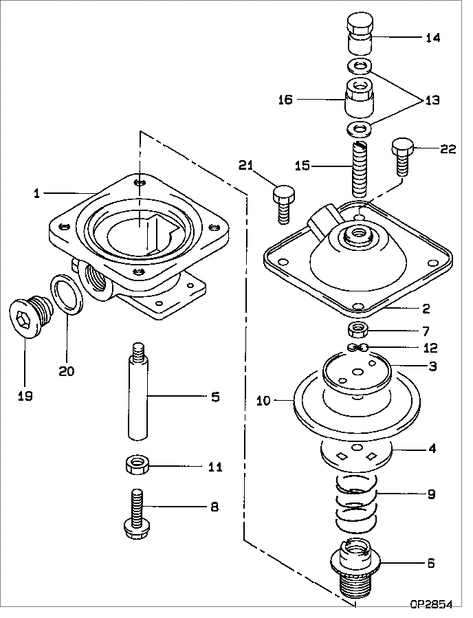
| 000. | [01] | 19260-00751 | COMPENSATOR SUB-AS | |
| 001. | [01] | 19261-10011 | HOUSING, BOOST COM | 22431-1020A |
| 002. | [01] | 19262-00050 | COVER SUB-ASSY | 22435-1020A |
| 003. | [01] | 19263-30010 | WASHER, THRUST | 22434-1030A |
| 004. | [01] | 19263-20010 | SEAT, SPRING, UPR | 22434-1020A |
| 005. | [01] | 19262-70010 | ROD, PUSH | 22432-1040A |
| 006. | [01] | 19263-50010 | BUSHING, GUIDE | 22375-1150A |
| 007. | [01] | 90160-06051 | NUT, HEXAGON | 22825-1480A |
| 008. | [01] | 19262-80020 | SCREW | 22432-1030A |
| 009. | [01] | 19263-40140 | SPRING, BOOST COMP | |
| 010. | [01] | 19263-10010 | DIAPHRAGM | 22361-1050A |
| 011. | [01] | 90170-06361 | NUT, HEXAGON | 92100-6040A |
| 012. | [01] | 94901-70490 | WASHER, WAVE | 22323-1180A |
| 013. | [02] | 94901-81020 | WASHER, COPPER PLA | 22867-1500A |
| 014. | [01] | 09103-10020 | NUT, CAP | 22342-1300A |
| 014. | [01] | 09103-10300 | NUT, CAP | |
| 015. | [01] | 09116-60080 | SCREW, STOP | 22865-1220A |
| 015. | [01] | 09116-60160 | SCREW, STOP | |
| 016. | [01] | 09116-90150 | NUT | |
| 016. | [01] | 94805-30130 | NUT, HEXAGON, W/HO | 22825-1060A |
| 019. | [01] | 09052-40041 | PLUG, SCREW | 22845-1300A |
| 020. | [01] | 94901-81040 | WASHER, COPPER PLA | 22843-1430A |
| 021. | [03] | 90107-06121 | BOLT, HEXAGON | 22815-2040A |
| 022. | [01] | 94904-50120 | BOLT, HEXAGON, W/ | 22815-2050A |
Include in #3:
09130-05024
as COMPENSATOR SUB-AS
19260-00751
Cross reference number
| Part num | Firm num | Firm | Name |
| 19260-00751 | COMPENSATOR SUB-AS |
Information:
(Diagnosing With Chassis Dynamometer)
1. Preparation of vehicle for wheel horsepower test (consult dynamometer manufacturer's operating instructions for specific details on correct operation). Always perform the Primary Engine Test procedure before vehicle is installed on chassis dynamometer.Calculate the allowable limits that the customer can expect from his engine and present these figures to him.Caterpillar engines are rated with the conditions that follow: Barometric pressure = 747 mm (29.4 in) of mercuryInlet air temperature = 29°C (85°F) at air cleaner inletFuel gravity = API gravity of 35 at 16°C (60°F)Measure and record these variables.a. Place vehicle on the chassis dynamometer. Tie the vehicle in a way that will not add any load to the drive wheels. Do not pull wheels down into dynamometer drive rolls.Check the radiator coolant level, crankcase oil level, tire pressure, tire condition, remove rocks from the tire tread and connect exhaust system.
Recapped tires should be run on a chassis dynamometer only at the customer's own risk.
b. Operate vehicle at 60% of rated speed with moderate load until oil and coolant temperatures reach their normal range for operation.
If there is a heavy vibration, drive shaft whip, tire bounce, etc., do not continue with dynamometer test until cause of the problem is corrected. Engines that have had new internal parts installed should be operated on a run-in schedule before operation at full load. For run-in schedule information, make reference to General Instructions section of this Service Manual.
2. Put transmission in direct gear and the differential in the highest speed ratio. Operate vehicle at maximum engine speed and increase chassis dynamometer load until a speed of 50 rpm less than rated speed is reached (continuity light should be on). Maintain this speed for one minute and record the engine speed and wheel horsepower. If horsepower is low and poor maintenance is suspected, remove air cleaner and check horsepower again to see if a plugged air cleaner could be the problem.3a. If the wheel horsepower is correct, find the set point (balance point) of the engine (speed at which the load stop pin just touches the torque spring or stop bar). At this point the continuity light should flicker (go off and on dimly).If the set point (balance point) is correct, then the low power complaint cannot be validated. No further test or repairs are necessary.If the set point (balance point) is low, see Procedure No. 4.3b. If the wheel horsepower is below the correct value, find the set point (balance point) of the engine (speed at which the load stop pin just touches the torque spring or stop bar). At this point the continuity light should flicker (go off and on dimly).If the set point (balance point) is correct, see Procedure No. 5.If the set point (balance point) is low, see Procedure No. 4.4. If the set point (balance point) is low, the high idle will have to be increased to raise the set point (balance point) to the correct rpm (the point at which the continuity light just