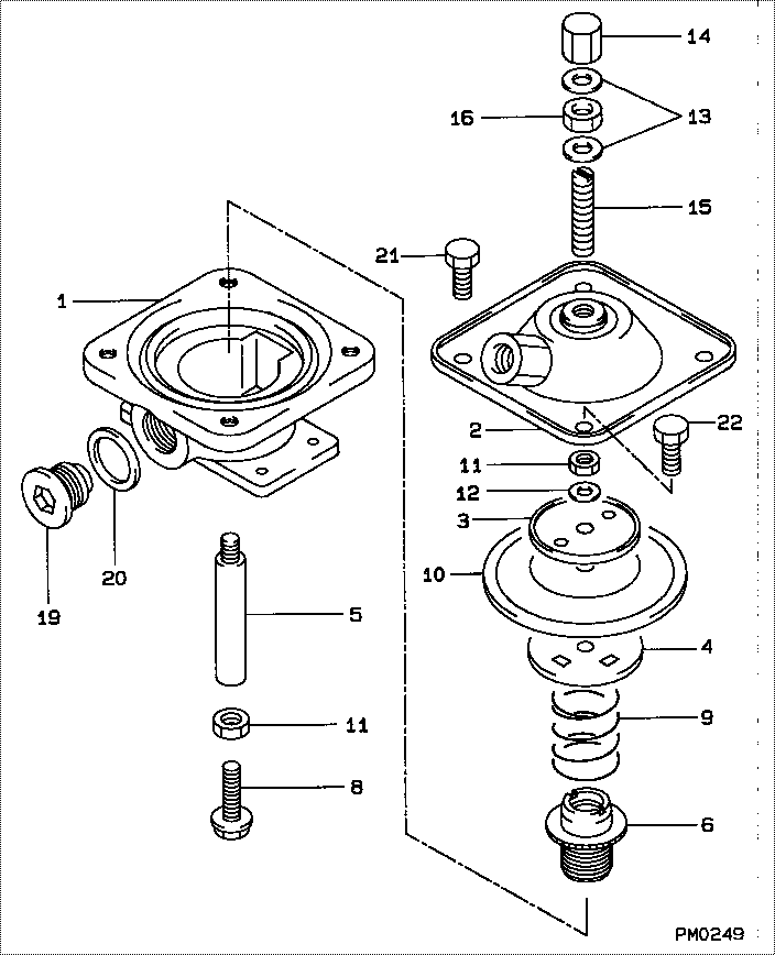
Information compensator sub-as

Rating:
Scheme ###:
| 000. | [01] | 19260-00470 | COMPENSATOR SUB-AS | 22430-1300 |
| 000. | [01] | 19260-00470 | COMPENSATOR SUB-AS | S2243-01300 |
| 000. | [01] | 19260-00470 | COMPENSATOR SUB-AS | |
| 001. | [01] | 19261-10030 | HOUSING, BOOST COM | 22431-1090A |
| 001. | [01] | 19261-10030 | HOUSING, BOOST COM | |
| 002. | [01] | 19262-00050 | COVER SUB-ASSY | 22435-1020A |
| 002. | [01] | 19262-00050 | COVER SUB-ASSY | |
| 003. | [01] | 19263-30010 | WASHER, THRUST | 22434-1030A |
| 003. | [01] | 19263-30010 | WASHER, THRUST | 19263-30010 |
| 004. | [01] | 19263-20010 | SEAT, SPRING, UPR | 19263-20010 |
| 004. | [01] | 19263-20010 | SEAT, SPRING, UPR | 22434-1020A |
| 005. | [01] | 19262-70020 | ROD, PUSH | 19262-70020 |
| 005. | [01] | 19262-70020 | ROD, PUSH | 22432-1410A |
| 006. | [01] | 19263-50010 | BUSHING, GUIDE | 19263-50010 |
| 006. | [01] | 19263-50010 | BUSHING, GUIDE | 22375-1150A |
| 008. | [01] | 19262-80010 | SCREW | |
| 008. | [01] | 19262-80010 | SCREW | 22815-3150A |
| 009. | [01] | 19263-40010 | SPRING, BOOST COMP | |
| 009. | [01] | 19263-40010 | SPRING, BOOST COMP | 22433-1320A |
| 010. | [01] | 19263-10010 | DIAPHRAGM | 22361-1050A |
| 010. | [01] | 19263-10010 | DIAPHRAGM | |
| 011. | [02] | 90160-06051 | NUT, HEXAGON | 22825-1480A |
| 011. | [02] | 90160-06051 | NUT, HEXAGON | 90160-06051 |
| 012. | [01] | 94901-70490 | WASHER, WAVE | 94901-70490 |
| 012. | [01] | 94901-70490 | WASHER, WAVE | 22323-1180A |
| 013. | [02] | 94901-81020 | WASHER, COPPER PLA | 22867-1500A |
| 013. | [02] | 94901-81020 | WASHER, COPPER PLA | 94901-81020 |
| 014. | [01] | 09103-10020 | NUT, CAP | 09103-10020 |
| 014. | [01] | 09103-10020 | NUT, CAP | 22342-1300A |
| 015. | [01] | 09116-60080 | SCREW, STOP | 09116-60080 |
| 015. | [01] | 09116-60110 | SCREW, STOP | |
| 015. | [01] | 09116-60080 | SCREW, STOP | 22865-1220A |
| 015. | [01] | 09116-60110 | SCREW, STOP | 22865-1490A |
| 016. | [01] | 94805-30130 | NUT, HEXAGON, W/HO | 94805-30130 |
| 016. | [01] | 94805-30130 | NUT, HEXAGON, W/HO | 22825-1060A |
| 019. | [01] | 09052-40041 | PLUG, SCREW | 22845-1300A |
| 019. | [01] | 09052-40041 | PLUG, SCREW | 09052-40041 |
| 020. | [01] | 94901-81040 | WASHER, COPPER PLA | 22843-1430A |
| 020. | [01] | 94901-81040 | WASHER, COPPER PLA | 94901-81040 |
| 021. | [03] | 90107-06121 | BOLT, HEXAGON | 90107-06121 |
| 021. | [03] | 90107-06121 | BOLT, HEXAGON | 22815-2040A |
| 022. | [01] | 94904-50120 | BOLT, HEXAGON, W/ | 22815-2050A |
| 022. | [01] | 94904-50120 | BOLT, HEXAGON, W/ | 94904-50120 |
Include in #3:
Cross reference number
| Part num | Firm num | Firm | Name |
| 19260-00470 | 22430-1300 | COMPENSATOR SUB-AS | |
| 22430-1300A | HINO | COMPENSATOR SUB-AS | |
| 22430-1300 | HINO | COMPENSATOR SUB-AS | |
| S2243-01300 | HINO | COMPENSATOR SUB-AS |
Information:
System Operation
The SLC 5/04 diagnostic indicators are located on the front of the following components: Power Supply, CPU and I/O Modules.The diagnostic indicators help trace the source of the fault. Faults can be found in the following components: Input devices, Output devices, Wiring and The controller.When the red LED is illuminated, there is a fatal error. A fatal error indicates that the processor is not communicating.
Illustration 1 g00563543
Diagram of the LED indicators
Illustration 2 g00562937
Functional Test
Check the electrical connectors and check the wiring.
Bodily contact with electrical potential can cause bodily injury or death.To avoid the possibility of injury or death, ensure that the main power supply has been disconnected before performing any maintenance or removing any modules.
Disconnect the power supply.
Check the electrical connectors and check the wiring for damage or bad connections.
Verify that all modules are properly seated.
Verify the status of the LED on the SLC 5/04.The results of the preceding procedure are in the following list:
All of the components are fully installed. All of the components are free of corrosion. All of the components are free of damage. All of the modules are properly seated. Proceed to 4.
The components are not fully installed. The components are not free of corrosion. The components are damaged. All of the modules are not properly seated. Repair the component. Verify that the repair resolves the problem. STOP.
Cycle the power.
Secure power to the PLC.
Energize the PLC.The results of the preceding procedure are in the following list:
No errors are displayed on the LED indicators. Stop.
Errors are displayed on the LED indicators. Proceed to 3.
Test the memory module.
To avoid damage to electronic components, do not remove the processor from the SLC 5/04 Chassis until all power is removed from the power supply.Do not expose memory modules to surfaces or areas that may typically hold an electrostatic charge.
Bodily contact with electrical potential can cause bodily injury or death.To avoid the possibility of injury or death, ensure that the main power supply has been disconnected before performing any maintenance or removing any modules.
Disconnect the power supply.
Remove the processor from the chassis.
Remove the memory module.
Install the processor.
Connect the power supply.
Energize the PLC.Reference: Maintenance Procedure, "Memory Module - Replace"The results of the preceding procedure are in the following list:
The "FLT" LED is flashing. Replace the memory module. Refer to Maintenance Procedure, "Memory Module - Replace". Stop.
The "FLT" LED is steady. Install the memory module. Proceed to 4.
Check the line voltage.
Reconnect the power supply.
Measure the line voltage at the terminals.
Verify the voltage of the power supply. The power supply voltage should be measured between 21.0 VDC and 28.0 VDC.The results of the preceding procedure are in the following list:
The line voltage is in the range. Install the processor in another chassis. Verify the diagnostic indicators. The fault is present. Replace the processor. Verify that the repair solves the problem. Refer to Maintenance Procedure, "Processor - Replace".
The line voltage is out of the range. Refer to Troubleshooting, "System Power". Stop.