Information compensator sub-as
Rating:
Scheme ###:
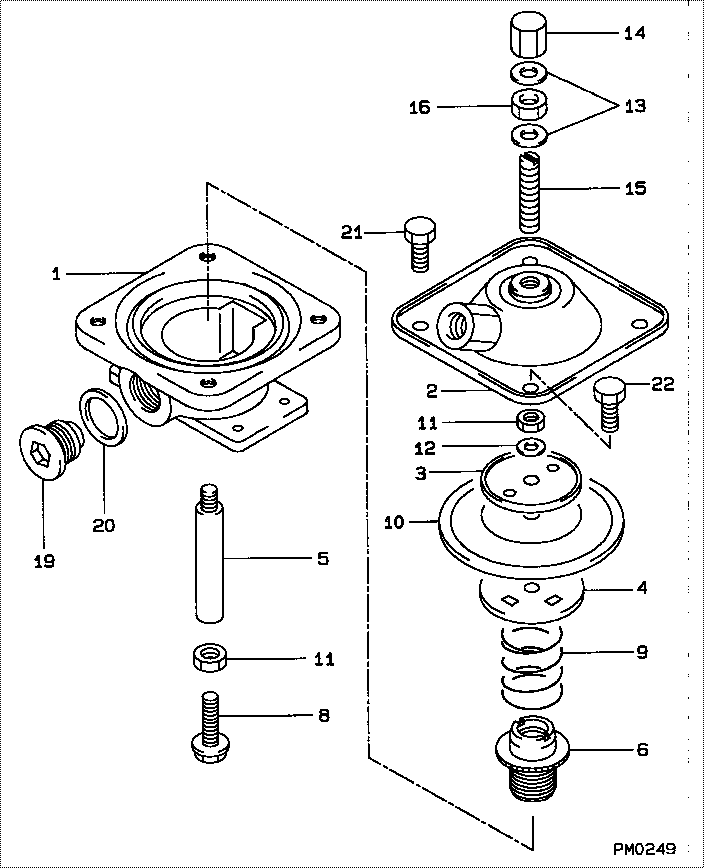
| 000. | [01] | 19260-00290 | COMPENSATOR SUB-AS | |
| 000. | [01] | 19260-00290 | COMPENSATOR SUB-AS | |
| 001. | [01] | 19261-10030 | HOUSING, BOOST COM | |
| 001. | [01] | 19261-10030 | HOUSING, BOOST COM | |
| 002. | [01] | 19262-00050 | COVER SUB-ASSY | |
| 002. | [01] | 19262-00050 | COVER SUB-ASSY | |
| 003. | [01] | 19263-30010 | WASHER, THRUST | |
| 003. | [01] | 19263-30010 | WASHER, THRUST | 19263-30010 |
| 004. | [01] | 19263-20010 | SEAT, SPRING, UPR | |
| 004. | [01] | 19263-20010 | SEAT, SPRING, UPR | 19263-20010 |
| 005. | [01] | 19262-70020 | ROD, PUSH | |
| 005. | [01] | 19262-70020 | ROD, PUSH | 19262-70020 |
| 006. | [01] | 19263-50010 | BUSHING, GUIDE | |
| 006. | [01] | 19263-50010 | BUSHING, GUIDE | 19263-50010 |
| 008. | [01] | 19262-80010 | SCREW | |
| 008. | [01] | 19262-80010 | SCREW | |
| 009. | [01] | 19263-40150 | SPRING, BOOST COMP | |
| 009. | [01] | 19263-40150 | SPRING, BOOST COMP | |
| 010. | [01] | 19263-10010 | DIAPHRAGM | |
| 010. | [01] | 19263-10010 | DIAPHRAGM | 19263-10010 |
| 011. | [02] | 90160-06051 | NUT, HEXAGON | 90160-06051 |
| 011. | [02] | 90160-06051 | NUT, HEXAGON | 85265-00085 |
| 012. | [01] | 94901-70490 | WASHER, WAVE | |
| 012. | [01] | 94901-70490 | WASHER, WAVE | 94901-70490 |
| 013. | [02] | 94901-81020 | WASHER, COPPER PLA | 94901-81020 |
| 013. | [02] | 94901-81020 | WASHER, COPPER PLA | 94901-81020 |
| 014. | [01] | 09103-10020 | NUT, CAP | 09103-10020 |
| 014. | [01] | 09103-10020 | NUT, CAP | 09103-10020 |
| 015. | [01] | 09116-60140 | SCREW, STOP | |
| 015. | [01] | 09116-60140 | SCREW, STOP | |
| 016. | [01] | 94805-30130 | NUT, HEXAGON, W/HO | |
| 016. | [01] | 94805-30130 | NUT, HEXAGON, W/HO | 94805-30130 |
| 019. | [01] | 09052-40041 | PLUG, SCREW | 09052-40041 |
| 019. | [01] | 09052-40041 | PLUG, SCREW | |
| 020. | [01] | 94901-81040 | WASHER, COPPER PLA | 94901-81040 |
| 020. | [01] | 94901-81040 | WASHER, COPPER PLA | 94901-81040 |
| 021. | [03] | 90107-06121 | BOLT, HEXAGON | 90107-06121 |
| 021. | [03] | 90107-06121 | BOLT, HEXAGON | |
| 022. | [01] | 94904-50120 | BOLT, HEXAGON, W/ | 94904-50120 |
| 022. | [01] | 94904-50120 | BOLT, HEXAGON, W/ |
Include in #3:
Cross reference number
| Part num | Firm num | Firm | Name |
| 19260-00290 | COMPENSATOR SUB-AS |
Information:
Start By:a. remove cylinder headb. remove oil panc. remove underframe 1. Remove bolt and remove cooling jet (1).2. Check the connecting rods and caps for their identification and location. The connecting rod and the rod cap should have the cylinder number etched on the right side indicated by the arrow. If not marked, etch each unmarked connecting rod/or cap during removal.3. Remove rod cap bolts (2) and the cap from the connecting rod. Remove the lower half of the bearing from the cap. 4. Push piston and connecting rod (4) away from the crankshaft, then remove upper half of the rod bearing (5).5. Remove the piston and connecting rod. The following steps are for the installation of the pistons and connecting rod assemblies.6. Put clean oil on piston rings, piston and cylinder bore. 7. Position the piston ring end gaps 120° apart and install tooling (A).8. With number one crankshaft throw at bottom center, install piston and connecting rod. Some engines use pistons which have the word "FRONT" stamped on the crown of the piston. Make sure the word "FRONT" is toward the front of the engine when the piston is installed. The etched number on the connecting rod must be on the right side and must be installed in the corresponding cylinder.9. Taking care to line up connecting rod and crankshaft, carefully tap piston into cylinder bore until tooling (A) comes off the piston.10. Before connecting rod comes in contact with crankshaft, install upper half of rod bearing. Be sure the bearing tab properly engages the slot in the connecting rod.11. Put engine oil on upper rod bearing surface, then tap piston down, guiding connecting rod onto crankshaft.12. Position lower half of rod bearing in corresponding numbered rod cap. Be sure the bearing tab engages the grove in the rod caps.13. Put engine on the lower rod bearing surface, then install the rod cap. Install the bearing cap on the connecting rod with the number on the bearing (rod) cap on the same side and same number as on the connecting rod.14. Put 2P2506 Thread Lubricant on the threads of the bolts. Install rod cap bolts (1) and tighten them to a torque of 130 7 N m (95 5 lb ft). Mark each bolt head and then tighten each bolt an additional 1/6 60 5° ( turn).15. Repeat the steps for the remainder of the pistons and connecting rods.End By:a. install underframeb. install oil panc. install cylinder headDisassemble & Assemble Pistons And Connecting Rods
Start By:a. remove pistons and connecting rods 1. Use tooling (A) and remove piston rings (1) from piston crown (2). 2. Remove snap ring and remove piston pin (3). Separate piston crown (2), piston skirt (4) and connecting rod (5). The connecting rod must be heated for the installation of the piston pin bearing. Do not use a torch.3. Heat connecting rod (5) in the area indicated by the illustration to a temperature of 175 to 260° C (347 to
Start By:a. remove pistons and connecting rods 1. Use tooling (A) and remove piston rings (1) from piston crown (2). 2. Remove snap ring and remove piston pin (3). Separate piston crown (2), piston skirt (4) and connecting rod (5). The connecting rod must be heated for the installation of the piston pin bearing. Do not use a torch.3. Heat connecting rod (5) in the area indicated by the illustration to a temperature of 175 to 260° C (347 to