Information pump assy, injecti
Rating:
Components :
| 001. | PUMP ASSY, INJECTI | 19100-09701 |
| 002. | BODY ASSY, INJECTI | 09010-08444 |
| 003. | COVER, BEARING | 09020-10250 |
| 004. | GOVERNOR ASSY, MEC | 09130-04020 |
| 005. | LEVER SET | 09129-10120 |
| 006. | COVER ASSY, GOVERN | 09145-00133 |
| 007. | TIMER ASSY, AUTOMA | 09180-02741 |
| 008. | PUMP ASSY, FUEL FE | 09210-02630 |
| 009. | PUMP ASSY, FUEL FE | 09210-03170 |
| 010. | COUPLING ASSY | 09250-00850 |
Scheme ###:
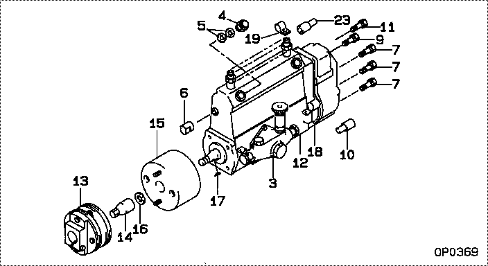
| 000. | [01] | 19100-09701 | PUMP ASSY, INJECTI | 22010-6860 |
| 003. | [01] | 09210-02630 | PUMP ASSY, FUEL FE | 22570-1500A |
| 003. | [01] | 09210-03170 | PUMP ASSY, FUEL FE | 22570-1730A |
| 004. | [01] | 09031-00380 | VALVE ASSY, OVERFL | 22107-1430A |
| 005. | [02] | 94901-02480 | WASHER | 22847-1940A |
| 006. | [01] | 09001-80010 | COVER, CONTROL RAC | 22118-1120 |
| 006. | [01] | 09001-80090 | COVER, CONTROL RAC | 22114-1250A |
| 007. | [05] | 94904-72690 | BOLT, W/WASHER | 22815-2410A |
| 009. | [01] | 91418-06201 | BOLT, W/WASHER | 22815-1290A |
| 010. | [01] | 09028-50030 | CAP | 22323-1210A |
| 011. | [01] | 94904-73910 | BOLT, W/WASHER | 22815-2820A |
| 012. | [01] | 09010-08444 | BODY ASSY, INJECTI | 22110-2532A |
| 013. | [01] | 09250-00850 | COUPLING ASSY | 22610-1640A |
| 014. | [01] | 09001-20220 | NUT, TIMER ROUND | 22511-1060A |
| 015. | [01] | 09180-02741 | TIMER ASSY, AUTOMA | 22510-2140A |
| 016. | [01] | 94901-40210 | WASHER, COUNTERSUN | 22867-1320A |
| 017. | [01] | 90458-04051 | KEY, WOODRUFF | 22895-1080A |
| 018. | [01] | 09130-04020 | GOVERNOR ASSY, MEC | |
| 018. | [01] | 09130-04021 | GOVERNOR ASSY, MEC | |
| 019. | [01] | 09039-10040 | CLIP, CORD | 22323-1190A |
| 023. | [01] | 09028-50050 | CAP | 22323-1320A |
Include in #3:
19100-09701
as PUMP ASSY, INJECTI
Cross reference number
| Part num | Firm num | Firm | Name |
| 19100-09701 | 22010-6860 | PUMP ASSY, INJECTI |
Information:
07Jul2011
(Revised 05Oct2011)
U-273
A-226
D-250
O-239
After Failure Only
PRODUCT SUPPORT PROGRAM FOR REPLACING THE FUEL INJECTION PUMP ON CERTAIN CP-533E AND CS-533E VIBRATORY SOIL COMPACTORS
1251 PS52050
This Program can only be administered after a failure occurs.The decision whether to apply the Program is made by the dealer. When reporting the repair, use "PS52050" as the Part Numberand "7755" as the Group Number. Use "96" as the Warranty Claim Description Code and use "Z" as the SIMS Description Code.
The information supplied in this service letter may not be valid after the termination date of this program.Do not perform the work outlined in this Service Letter after the termination date without first contacting your Caterpillar product analyst.
This Revised Service Letter replaces the 07Jul2011 (Revised 05Oct2011) Service Letter. Changes have been made to the Action Required.
TERMINATION DATE
31Jan2012
PROBLEM
The existing fuel injection pump can fail on certain CP-533E and CS-533E Vibratory Soil Compactors. If the existing fuel injection pump fails it can cause low power, poor starting, fuel leaks, and engine performance issues.
AFFECTED PRODUCT
Model Identification Number
CP-533E ASM00310-00311, 313, 316-380
BZG00466-01134
TLH00101-00147
CS-533E ASL03060, 3068, 3092, 3103, 3106, 3110, 3121, 3125-3126, 3130-3135, 3138-3872
BZE01120-02370
TBE00148-00237
TJL00100-01472, 1474-1628, 1630-1631, 1633-1637, 1639-1678
PARTS NEEDED
Qty
Part Number Description
1 2845000 PUMP GP-F INJ -B
In order to allow equitable parts availability to all participating dealers, please limit your initial parts order to not exceed 1% of dealership population. This is an initial order recommendation only, and the ultimate responsibility for ordering the total number of parts needed to satisfy the program lies with the dealer.
ACTION REQUIRED
Replace the failed fuel injection pump. Refer to the engine's Disassembly and Assembly, "Fuel Injection Pump - Remove and Install".
While carrying out "Fuel Injection Pump - Remove", please ensure that the fuel injection pump gear backlash is removed and the fuel injection pump locking bolt is tightened to a torque of 17 N.m (13 lb ft).
Fuel injection pumps that have not been locked correctly will have the claim rejected or debited.
After the new fuel injection pump has been installed, carry out checks for air in the fuel. Refer to the engine's Testing and Adjusting, "Air in Fuel - Test".
To ensure correct priming of the fuel system on first start-up, follow the procedure below.
1. Ensure that all low pressure fuel connections and high pressure fuel lines are installed correctly.
2. Turn the ignition key to the RUN position. Leave the ignition key in the RUN position for three minutes.
3. Crank the engine with the throttle lever in the CLOSED position until the engine starts.
Note: If necessary, loosen the union nuts on the fuel injection lines at the connection with the fuel injector until fuel is evident. Stop cranking the engine. Tighten the union nuts to a torque of 30 N.m (22 lb ft).
4. Start the engine and run the engine at low idle for one minute.
5. Cycle the throttle lever from the low idle position to the high idle position three times. The cycle time for the throttle lever is one second to six seconds for one complete cycle.
6. Check for leaks in the fuel system.
DOCUMENTATION PROCEDURE
Please ensure that when submitting the