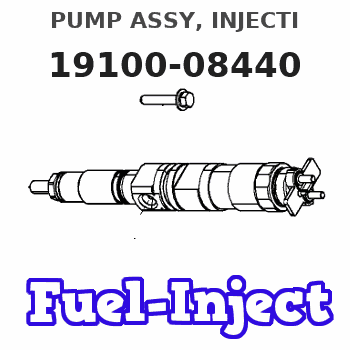
Information pump assy, injecti
Nozzle:
0935004860
Rating:
KIT List:
| Body assy, injecti | 1904400430 |
| Timer assy, automa | No Application |
| Pump assy, fuel fe | 1922900060 |
| Governor assy, mec | 1908900210 |
Components :
| 001. | PUMP ASSY, INJECTI | 19100-08440 |
| 002. | BODY ASSY, INJECTI | 09010-09160 |
| 003. | TIMER ASSY, AUTOMA | 09180-03010 |
| 003. | TIMER ASSY, AUTOMA | 09180-03010 |
| 004. | PUMP ASSY, FUEL FE | 09210-01800 |
| 005. | COUPLING ASSY | 09250-00931 |
| 006. | GOVERNOR ASSY, MEC | 19080-03320 |
| 007. | SWITCH KIT, CONTRO | 09009-90602 |
Scheme ###:
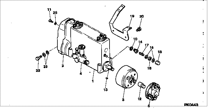
| 000. | [01] | 19100-08440 | PUMP ASSY, INJECTI | ME091893 |
| 001. | [01] | 09010-09160 | BODY ASSY, INJECTI | ME728340 |
| 002. | [01] | 19080-03320 | GOVERNOR ASSY, MEC | ME728342 |
| 003. | [01] | 09180-03010 | TIMER ASSY, AUTOMA | ME728334 |
| 004. | [01] | 09210-01800 | PUMP ASSY, FUEL FE | ME702667 |
| 005. | [01] | 09250-00931 | COUPLING ASSY | ME728335 |
| 010. | [01] | 94901-80710 | WASHER, COPPER PLA | ME702915 |
| 011. | [08] | 94904-44010 | BOLT | ME728336 |
| 011. | [04] | 94904-76890 | BOLT, W/WASHER | ME728978 |
| 012. | [01] | 09001-20340 | NUT, TIMER ROUND | ME728343 |
| 013. | [01] | 90458-05750 | KEY, WOODRUFF | ME702920 |
| 014. | [01] | 09001-80152 | COVER, CONTROL RAC | ME702921 |
| 015. | [02] | 94901-80350 | WASHER, COPPER PLA | ME702922 |
| 016. | [01] | 94805-30100 | NUT, HEXAGON, W/HO | ME702923 |
| 017. | [01] | 09002-60050 | SCREW, ADJUSTING | ME702924 |
| 018. | [01] | 09003-20040 | CAP | ME702858 |
| 019. | [01] | 09069-11050 | BRACKET, STOP WIRE | ME702672 |
| 020. | [02] | 91410-08141 | BOLT, W/WASHER | ME702925 |
| 022. | [01] | 94918-00050 | SCREW, HOLLOW | ME702926 |
| 023. | [02] | 09022-20060 | WASHER, FUEL PIPE | ME702927 |
| 025. | [08] | 94901-36520 | WASHER, PLATE, SK | ME728337 |
Include in #3:
19100-08440
as PUMP ASSY, INJECTI
Cross reference number
| Part num | Firm num | Firm | Name |
| 19100-08440 | ME091893 | PUMP ASSY, INJECTI | |
| ME091893 | MITSUBISHI | PUMP ASSY, INJECTI |
Information:
Measurement of Distortion of Cylinder Head Bottom Surface
Place a straight edge on the bottom surface of the cylinder head, measure the amount of surface distortion using feeler gages, and, if the limit value is exceeded, reface the surface with a surface grinder.
Measurement of distortion of cylinder head bottom surfaceMeasurement of Rocker Arm Inside Diameter and Rocker Shaft Diameter
Measure the inside diameter of the rocker arm (bushing) and the diameter of the rocker shaft to calculate the clearance between the rocker arm and shaft, and replace the rocker arm if the clearance is within the limit value. If the limit value is exceeded, replace the rocker arm and shaft.
Measurement of rocker arm inside diameter and rocker shaft diameterMeasurement of Valve Spring Perpendicularity and Free Length
Inspect each valve spring for perpendicularity and free length, and, if the limit value is exceeded, replace the valve.
Measurement of valve spring perpendicularity and free lengthMeasurement of Pushrod Runout
If the pushrod runout exceeds the standard value, replace the pushrod. The standard value above is based on dial gage reading.
Measurement of pushrod runoutMeasurement of Valve Stem Diameter
If the stem diameter exceeds the limit value, replace the valve stem. Also replace the valve stem if it is unevenly worn.
Measurement of valve stem diameterMeasurement of Clearance Between Valve Stem and Valve Guide
Measure the valve guide bore with and internal bore micrometer.Because the valve guide wears more rapidly at the upper and lower ends, measure the diameter at both ends in two crossing directions. If the limit is exceeded, replace worn parts. Remove carbon deposits from the valve and valve guide before measuring the clearance.
Measurement of valve guide inside diameter
Removal of valve guideReplacement of Valve Guides
(1) To remove the valve guides, use the valve guide remover.(2) To press-fit the valve guides, use the valve guide installer and a press.
Be sure to use the valve guide installer in order to drive the valve guide to the prescribed depth.
(3) After installing the valve guide, insert a new valve and check the smoothness of the movement.(4) When the valve guide is replaced, check the contact of the valve with the valve seat.
Installation of valve guideInspection of Valve Faces
Coat the valve face lightly with shinmeitan, and use the valve lapper to inspect the valve contact with the valve seat. If the contact is not uniform and the valve is defective, or if a limit is exceeded, correct or replace the valve and valve seat.
Inspection of valve face (a) Inspect the valve face after the valve guide is inspected or replaced.(b) When pressing the valve coated with shinmeitan against the valve seat, do not rotate the valve.(c) After the valve or valve seat is corrected or replaced, lap the valve against the valve seat.
Valve seat contact with seat
Valve contact with seatReplacement of Valve Seats
(1) Removal of valve seatWeld a stud or bar to the valve seat, insert a shaft into the valve guide bore from the top of the cylinder head, and drive the seat off the cylinder head. When welding the stud, do