Information pump assy, injecti
Rating:
Scheme ###:

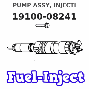
| 000. | [01] | 19100-08240 | PUMP ASSY, INJECTI | 62227-11940 |
| 000. | [01] | 19100-08241 | PUMP ASSY, INJECTI | 62227-11941 |
| 003. | [01] | 09010-09132 | BODY ASSY, INJECTI | |
| 004. | [01] | 19080-03190 | GOVERNOR ASSY, MEC | |
| 005. | [02] | 94904-76880 | BOLT, W/WASHER | |
| 005. | [02] | 94904-44000 | BOLT | |
| 006. | [01] | 09001-80410 | COVER, CONTROL RAC | |
| 007. | [01] | 94905-03400 | NUT, HEXAGON | |
| 008. | [01] | 94901-50730 | WASHER, SPRING | |
| 009. | [01] | 90458-05750 | KEY, WOODRUFF | |
| 010. | [01] | 09210-01761 | PUMP ASSY, FUEL FE | |
| 011. | [01] | 09006-10011 | COVER, PRIMING PUM | 09006-10011 |
| 012. | [01] | 94901-81550 | WASHER, COPPER PLA | |
| 014. | [01] | 94914-03690 | O-RING | |
| 017. | [01] | 94904-44070 | BOLT | |
| 017. | [01] | 94904-76910 | BOLT, W/WASHER | |
| 018. | [04] | 94904-76890 | BOLT, W/WASHER | |
| 018. | [04] | 94904-44010 | BOLT | |
| 021. | [08] | 94901-36520 | WASHER, PLATE, SK | |
| 022. | [01] | 94904-44060 | BOLT | |
| 022. | [01] | 94904-76900 | BOLT, W/WASHER |
Include in #3:
19100-08241
as PUMP ASSY, INJECTI
Cross reference number
| Part num | Firm num | Firm | Name |
| 19100-08241 | 62227-1194 | PUMP ASSY, INJECTI |
Information:
Inspection and Adjustment of Valve Clearance
Inspect and adjust valve clearances when the engine is cold. (1) Inspecting valve clearance(a) Inspect the valve clearance in the firing order by turning the crankshaft 180° in the normal direction to bring each piston to the top dead center on the compression stroke. (b) Attach a socket and ratchet handle to the crankshaft pulley tightening nut, and turn the crankshaft.(c) When the No. 1 piston is at the top dead center on the compression stroke, the "0" line stamped on the circumference of the crankshaft pulley is aligned with the pointer of the timing gear case, and the inlet and exhaust valves are not lifted off their seats by the pushrods. (d) Insert a feeler gage between the rocker arm and valve cap to inspect the clearance.
Checking top dead center cylinder of No. 1 piston compression stroke (1)
Checking top dead center cylinder of No. 1 piston compression stroke (2)(2) Adjusting valve clearance(a) Loosen the lock nut, insert a feeler gage between the rocker arm and valve cap, and while measuring the clearance, tighten or loosen the adjusting screw until the feeler gear moves slightly tight.(b) After adjusting the clearance, securely tighten the locknut, and inspect the clearance again.
Adjusting valve clearanceDraining of Fuel System
If water collects in an amount greater than the specified amount on the bottom of the fuel filter, it may enter the fuel system.(1) Fuel filter (distributor-type fuel injection pump)(a) Loosen the drain plug at the bottom of the fuel filter.
Draining of fuel filter (1)(b) Push the priming pump about seven times to feed the fuel rapidly to accelerate the draining of the fuel system.(c) After draining the fuel system, securely tighten the drain plug.(d) After draining the fuel system, be sure to bleed the fuel system.
When the fuel system is drained, the fuel is discharged at the same time. Thoroughly wipe off any fuel spilled on the surrounding parts.
Draining of fuel filter (2)Bleeding of Fuel System
Start to bleed the fuel system from a location closest to the fuel tank, and move toward the engine in the order of the fuel filter and the fuel injection pump.(1) Fuel filter (distributor-type fuel injection pump)(a) Loosen the air vent plug of the fuel filter with a wrench.
Bleeding of fuel filter (1)(b) Apply a cloth to the air vent plug, and repeatedly push the priming pump. The bleeding procedure is completed when no air bubbles appear in the fuel coming out of the air vent plug.(c) Securely tighten the air vent plug.
Bleeding of fuel filter (2)(2) Fuel filter (in-line fuel injection pump)(a) Loosen the air vent plug on the fuel filter by about 1.5 turns.(b) Loosen the priming pump cap of the fuel feed pump by turning it counterclockwise, and move it up and down.(c) Tighten the air vent plug when no air bubbles appear in the fuel coming out of it.
Bleeding fuel filter (in-line fuel injection pump)(3) Fuel injection pump (in-line fuel injection pump)(a) Loosen the air vent plug of the fuel