Information pump assy, injecti
Rating:
Components :
| 001. | PUMP ASSY, INJECTI | 19100-07931 |
| 002. | BODY ASSY, INJECTI | 09010-07441 |
| 003. | COVER, BEARING | 09020-10410 |
| 004. | GOVERNOR ASSY, MEC | 09130-03141 |
| 005. | COVER ASSY, GOVERN | 09145-00133 |
| 006. | TIMER ASSY, AUTOMA | 09180-03190 |
| 007. | PUMP ASSY, FUEL FE | 09210-00920 |
| 008. | COUPLING ASSY | 09250-00720 |
Scheme ###:
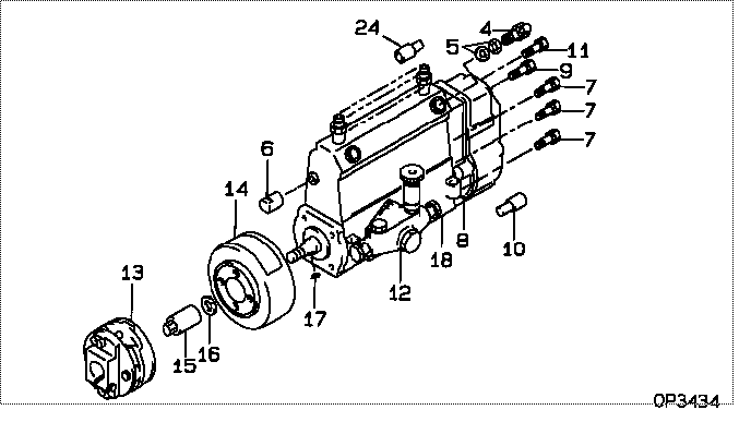
| 000. | [01] | 19100-07931 | PUMP ASSY, INJECTI | 22010-6081 |
| 004. | [01] | 09031-00240 | VALVE ASSY, OVERFL | 22107-1290A |
| 005. | [02] | 94901-02480 | WASHER | 22847-1940A |
| 006. | [01] | 09001-80090 | COVER, CONTROL RAC | 22114-1250A |
| 007. | [05] | 94904-72690 | BOLT, W/WASHER | 22815-2410A |
| 008. | [01] | 09130-03141 | GOVERNOR ASSY, MEC | |
| 009. | [01] | 91418-06201 | BOLT, W/WASHER | 22815-1290A |
| 010. | [01] | 09028-50030 | CAP | 22323-1210A |
| 011. | [01] | 94904-73910 | BOLT, W/WASHER | 22815-2820A |
| 012. | [01] | 09210-00920 | PUMP ASSY, FUEL FE | 22570-1250A |
| 013. | [01] | 09250-00720 | COUPLING ASSY | 22610-1502A |
| 014. | [01] | 09180-03190 | TIMER ASSY, AUTOMA | 22510-2420A |
| 015. | [01] | 09001-20180 | NUT, TIMER ROUND | 22511-1070A |
| 016. | [01] | 94901-50590 | WASHER, SPRING | 22877-1620A |
| 017. | [01] | 94913-00210 | KEY, WOODRUFF | 22895-1010A |
| 018. | [01] | 09010-07441 | BODY ASSY, INJECTI | 22110-2290A |
| 024. | [01] | 09028-50050 | CAP | 22323-1430A |
Include in #3:
19100-07931
as PUMP ASSY, INJECTI
Cross reference number
| Part num | Firm num | Firm | Name |
| 19100-07931 | 22010-6081 | PUMP ASSY, INJECTI |
Information:
2. Specifications (standard) FUEL INJECTION NOZZLE
1. Inspection(1) Injection pressure (valve opening pressure) test(a) Install the injection nozzle on the tester. Slowly operate the tester handle to bleed (remove) air from the tester.(b) Operate the tester handle at a speed of one stroke per second to make a slow increase in pressure until the valve in the injection nozzle starts to open. Read the maximum gauge pressure at the instant fluid flows from the tip.(c) If the injection pressure is incorrect, disassemble the nozzle and change the thickness of the washer.
Fuel injection nozzle ready for test
Removing tip from injection nozzle An increase or decrease of washer thickness by 0.1 mm (0.004 in.) will vary the injection pressure by 10 kgf/cm 2 (142 psi) [981 kPa]. 10 kinds of washer are available in thicknesses from 1.25 mm (0.049 2 in.) to 1.70 mm (0.066 9 in.) in increments of 0.05 mm (0.002 0 in.).
When the injection nozzles are tested, be sure to wear eye protection. Fuel comes from the orifices in the nozzle tip with high pressure. The fuel can pierce (go through) the skin and cause serious injury to the operator. Keep the tip of the nozzle pointed away from the operator and into the fuel collector.
(2) Orifice restriction test (a) Look at the orifice discharge pattern (shape of discharge) when fluid begins to flow through the injection nozzle. The discharge must be straight. Any change is an indication of a bad nozzle. (b) Operate the tester handle at a speed of one stroke per second to make sure the discharge is straight.
Orifice restriction test3. Nozzle tip washing and replacement (a) Loosen the retaining nut and remove the tip from the injection nozzle. Wash the needle valve and body in clean diesel fuel. After washing, put the needle valve in the body in clean diesel fuel.
Do not hit the tip when removing it from the injection nozzle.
Washing nozzle tip Keep the need valves with their respective bodies. Do not use needle valves or bodies with other bodies or needle valves.(b) After cleaning the tip, install it in the nozzle and tighten the retaining nut to the specified torque. (c) If the injection nozzle is still bad after the tip has been washed, replace the tip. a) Do not touch the sliding surface of the needle valve.b) When installing the new nozzle tip, remove synthetic resin film from the tip and slide the needle valve in the body in clean diesel fuel to wash off inhibitor completely.2. Disassembly and assembly
Disassembly sequence and inspection points1 Retaining nut2 Nozzle tip assembly3 Piece4 Pin5 Spring6 Washer7 BodyFUEL INJECTION PUMP
1. Test on engine Check the injection pump for items listed in the chart below and replace it if defective. Do not attempt to make repairs by disassembling. 2. Disassembly
Disassembly sequence1 Tappet guide pin2 Lock plate3 Tappet4 Tappet adjusting shim5 Lower spring seat6 Plunger7 Plunger spring8 Upper spring seat9 Control sleeve10 Control rack11 Delivery valve holder12 O-ring13 Delivery valve spring14 Delivery valve gasket15 Delivery valve16