Information pump assy, injecti
Rating:
Compare Prices: .
As an associate, we earn commssions on qualifying purchases through the links below

Remanufactured Fuel Injection Pump fits John Deere 9500 9600 RE32064 RE46264 fits Denso 191000-5870 191000-5871 191000-5872 191000-5873 191000-8590
Parts ASAP Compatible with John Deere Combine(s) 9500 (Straight Hand Primer), 9600 (Straight Hand Primer) || Replaces John Deere OEM Number(s) RE46264, RE32064 || Replaces Denso Mfg Number(s) 191000-5870, 191000-5871, 191000-5872, 191000-5873, 191000-8590
Parts ASAP Compatible with John Deere Combine(s) 9500 (Straight Hand Primer), 9600 (Straight Hand Primer) || Replaces John Deere OEM Number(s) RE46264, RE32064 || Replaces Denso Mfg Number(s) 191000-5870, 191000-5871, 191000-5872, 191000-5873, 191000-8590

$14,844.25
15 Sep 2024
US: IrynaMizeriia
Generic Replacement Parts For Auto Moto Truck Tractor OEM For Remanufactured Fuel Injection Pump fits John Deere 9500 9600 RE32064 Index-GT988-18242, Black
Generic OEM Precision: Engineered to the exact specifications of original equipment manufacturers, ensuring a perfect fit and seamless integration into your vehicle's system. || Reliable Performance: Our replacement parts deliver consistent and reliable performance, maintaining the efficiency and longevity of your automobile, motorcycle, truck, or tractor. || Quality Assurance: Each part undergoes rigorous testing to meet stringent quality standards, providing peace of mind and confidence in your vehicle's operation. || Wide Compatibility: Our extensive inventory covers a broad range of makes and models, offering solutions for various automotive, motorcycle, truck, and tractor applications. || Customer Satisfaction: Backed by our commitment to exceptional customer service, we strive to assist you in finding the right OEM replacement parts to meet your specific needs and requirements.
Generic OEM Precision: Engineered to the exact specifications of original equipment manufacturers, ensuring a perfect fit and seamless integration into your vehicle's system. || Reliable Performance: Our replacement parts deliver consistent and reliable performance, maintaining the efficiency and longevity of your automobile, motorcycle, truck, or tractor. || Quality Assurance: Each part undergoes rigorous testing to meet stringent quality standards, providing peace of mind and confidence in your vehicle's operation. || Wide Compatibility: Our extensive inventory covers a broad range of makes and models, offering solutions for various automotive, motorcycle, truck, and tractor applications. || Customer Satisfaction: Backed by our commitment to exceptional customer service, we strive to assist you in finding the right OEM replacement parts to meet your specific needs and requirements.

$5,475.00
21 Apr 2023
34.25[15.41] Pounds
US: All States Ag Parts
Remanufactured Fuel Injection Pump fits John Deere 9500 9600 RE32064
All States Ag Parts Parts A.S.A.P. Compatible with John Deere Combine(s) 9500 (Straight Hand Primer), 9600 (Straight Hand Primer) || Replaces John Deere OEM nos RE46264, RE32064 || Replaces Denso Mfg nos 191000-5870, 191000-5871, 191000-5872, 191000-5873, 191000-8590 || For a Used version of this sku use 429380 || Additional Handling & Oversize Fees Apply To This Item
All States Ag Parts Parts A.S.A.P. Compatible with John Deere Combine(s) 9500 (Straight Hand Primer), 9600 (Straight Hand Primer) || Replaces John Deere OEM nos RE46264, RE32064 || Replaces Denso Mfg nos 191000-5870, 191000-5871, 191000-5872, 191000-5873, 191000-8590 || For a Used version of this sku use 429380 || Additional Handling & Oversize Fees Apply To This Item
Components :
| 001. | PUMP ASSY, INJECTI | 19100-05873 |
| 002. | BODY ASSY, INJECTI | 09010-08112 |
| 003. | PUMP ASSY, FUEL FE | 09210-02110 |
| 004. | GOVERNOR ASSY, ELE | 09550-00110 |
Scheme ###:
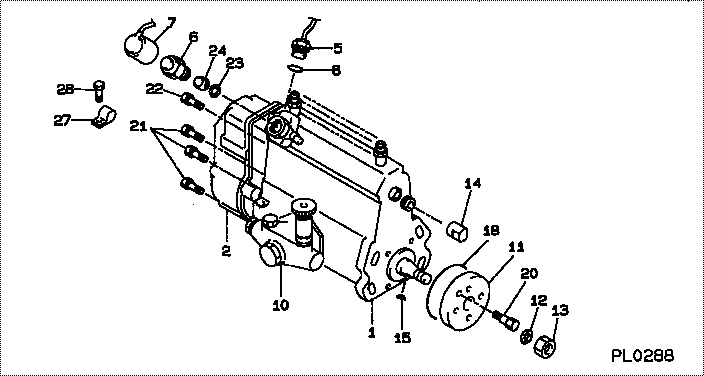
| 000. | [01] | 19100-05873 | PUMP ASSY, INJECTI | RE32064 |
| 001. | [01] | 09010-08112 | BODY ASSY, INJECTI | |
| 002. | [01] | 09550-00110 | GOVERNOR ASSY, ELE | |
| 005. | [01] | 07150-01661 | SENDER ASSY, TEMPE | |
| 006. | [01] | 09603-00190 | SOLENOID ASSY, FUE | |
| 007. | [01] | 09604-50450 | WIRE SUB-ASSY | |
| 008. | [01] | 94914-04270 | O-RING | |
| 010. | [01] | 09210-02110 | PUMP ASSY, FUEL FE | |
| 011. | [01] | 09255-10550 | BLOCK, COUPLING | |
| 012. | [01] | 94901-50900 | WASHER, SPRING | |
| 013. | [01] | 94905-03570 | NUT, HEXAGON | |
| 014. | [01] | 09001-80140 | COVER, CONTROL RAC | |
| 015. | [01] | 90458-04051 | KEY, WOODRUFF | |
| 018. | [01] | 94914-03430 | O-RING | |
| 020. | [01] | 94904-06950 | BOLT, HEXAGON | |
| 021. | [06] | 91518-06161 | BOLT, W/WASHER | |
| 022. | [01] | 91418-08161 | BOLT, W/WASHER | |
| 023. | [01] | 09606-40110 | WASHER | |
| 024. | [01] | 09653-00071 | FILTER, SUB-ASSY | |
| 027. | [01] | 94935-06110 | CLIP, CORD | |
| 028. | [01] | 91107-05081 | BOLT, HEXAGON |
Include in #3:
19100-05873
as PUMP ASSY, INJECTI
Cross reference number
| Part num | Firm num | Firm | Name |
| 19100-05873 | RE32064 | PUMP ASSY, INJECTI |
Information:
Starter, Preheat Structure And Operation
Starter
* This starter uses planetary gears as its reduction gearing mechanism.Alternator
<24V-35A> Circuit Diagram
Troubleshooting
Power And Charging
Engine Starting, Preheating and Stopping
#180 to #249 Relay, #250 to #349 Sensor, #750 to #859 Other
#187 Inspection of starter relay
* Perform continuity check and operation check, and if any fault is found, replace the relay.#231 Inspection of safety relay
* Measure the resistance values between terminals 2 and 3. * If the measured value deviates from the standard value, replace the relay.#262 Inspection of water temperature sensor
* Dip the sensor in a container filled with engine oil.* Raise the oil temperature to the specified one while stirring oil.* Measure the resistance between terminals 1 and 2. * If the measured value deviates from the standard value, replace the sensor. (See Gr14.)#764 Inspection of glow plug
* Measure the resistance value of glow plug as shown. * If the measured value deviates from the standard value, replace the glow plug. (See Gr11.)#930 Starter
* Before removing the starter, disconnect the (-) battery cable and insulate the cable and the (-) battery terminal with tape.* It is dangerous to leave the (-) battery cable connected since the battery cable is always present at terminal B.
Disassembly Sequence1 Stopper ring2 Pinion stopper3 Pinion4 Spring5 Magnetic switch6 Rear bracket7 Brush spring8 Brush (-)9 Brush holder10 Brush (+)11 Yoke12 Rear bearing13 Washer14 Armature15 Ball16 Cover17 Rubber packing18 Planetary gear19 Rubber packing20 Plate21 E-ring22 Gear shaft23 Washer24 Internal gear25 Overrunning clutch26 Lever27 Front bearing28 Oil seal29 Front bracketX: Non-reusable parts
* When the armature is removed, the ball may come out with it. Take care not to lose the ball.
* Do not remove the rear and front bearing unless defects are evident.* It is not necessary to remove the pinion when only the motor section needs to be disassembled for inspection, like when inspecting brushes and related parts.* Be sure to remove the pinion before disassembling any other parts. Assembly SequenceFollow the disassembly sequence in reverse.* Whenever the magnetic switch is replaced, the pinion gap must be adjusted.* The rubber packing is serviceable if any defect is not found.Service Standards (Unit: mm) Lubricant and/or Sealant Special Tools Work Before Disassembly Mating Mark: Rear bracket and yoke Disassembly Procedure Disassembly: Pinion* For removal of the pinion, the current must be supplied to the starter such that the pinion springs out.
* When the starter is energized, the pinion will spring out and rotate. Be careful not to touch it with your hands.* The magnetic switch may become very hot during inspections. Be careful when touching it.
* Do not energize the pull-in coil P for longer than 10 seconds, and do not energize the holding coil H for longer than 30 seconds. If these periods are exceeded, the coils may overheat and burn out.* To make the pinion spring out, be sure to energize the starter such that its parts are positioned correctly. If the starter is not energize and the lever is pulled to make the pinion come out, the front bracket and/or