Information pump assy, injecti
Nozzle:
0935002080
Rating:
KIT List:
| Timer assy, automa | 0918030060 |
| Pump assy, fuel fe | 1922900060 |
Components :
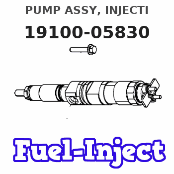
| 001. | PUMP ASSY, INJECTI | 19100-05830 |
| 002. | BODY ASSY, INJECTI | 09010-04034 |
| 003. | COVER, BEARING | 09020-10410 |
| 004. | TIMER ASSY, AUTOMA | 09180-01210 |
| 005. | PUMP ASSY, FUEL FE | 09210-00920 |
| 006. | COUPLING ASSY | 09250-00270 |
| 007. | GOVERNOR ASSY, MEC | 19080-01610 |
Scheme ###:
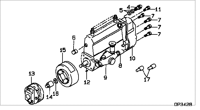
| 000. | [01] | 19100-05830 | PUMP ASSY, INJECTI | 22010-5480 |
| 004. | [01] | 09031-00130 | VALVE ASSY, OVERFL | 22107-1090A |
| 005. | [02] | 94901-02480 | WASHER | 22847-1940A |
| 006. | [01] | 09001-80290 | COVER, CONTROL RAC | 22114-1020A |
| 007. | [06] | 94904-71150 | BOLT, W/WASHER | 6 306 1001 00 |
| 008. | [01] | 09010-04034 | BODY ASSY, INJECTI | 22110-1482A |
| 009. | [01] | 09210-00920 | PUMP ASSY, FUEL FE | 22570-1250A |
| 010. | [01] | 19080-01610 | GOVERNOR ASSY, MEC | 22310-3780A |
| 011. | [01] | 94904-73910 | BOLT, W/WASHER | 22815-2820A |
| 012. | [01] | 94913-00210 | KEY, WOODRUFF | 22895-1010A |
| 013. | [01] | 09250-00270 | COUPLING ASSY | 22610-1080A |
| 014. | [01] | 09001-20180 | NUT, TIMER ROUND | 22511-1070A |
| 015. | [01] | 09180-01210 | TIMER ASSY, AUTOMA | 22510-1190A |
| 016. | [01] | 94901-50590 | WASHER, SPRING | 22877-1620A |
| 017. | [02] | 09028-50030 | CAP | 22323-1210A |
Include in #3:
19100-05830
as PUMP ASSY, INJECTI
Cross reference number
| Part num | Firm num | Firm | Name |
| 19100-05830 | 22010-5480 | PUMP ASSY, INJECTI | |
| 22010-5480 | HINO | PUMP ASSY, INJECTI |
Information:
Removing:
6-1Cut through the starter gear ring with a hard chisel and remove.Fig. 6-1Refitting:
1. Heat the starter gear ring to a temperature of 120 deg. C. Place the starter gear ring with the bevelled side of the teeth facing away from flywheel.
6-22. Locate the starter gear ring on the flywheel and tap it into position so that it seats against the shoulder.Fig. 6-2Removing And Fitting A Radial Sealing Ring On The Flywheel Side
It is assumed that the flywheel has been dismantled. Removing:
6-3Apply puller No. 142700 and draw off radial sealing ring.Fig. 6-3Refitting:
6-41. Mount guide-piece of device onto crankshaft.Fig. 6-4
6-52. Lightly grease the sealing lip of the new radial seal. Place seal on guide-piece with lip facing towards crankcase and press in with device No. 142530.Fig. 6-5 Inspect crankshaft in the zone of radial seal contact. If a friction groove has been formed by the radial seal, displace the complete cover by adding gaskets accordingly.Dismantling, Installing And Sealing The Cover On The Flywheel Side (As from 3-cylinder engine)
The flywheel has already been removed.Dismantling:
1. Remove the bolts in the oil sump securing the cover on the flywheel side and the bolts securing the cover to the crankcase. Remove cover and gasket. Renew radial sealing ring. Inspect crankshaft in the zone of radial seal contact. If a friction groove has been formed by the radial seal, displace the latter in the cover.Installing:
6-112. Adhere new gasket to crankcase. Trim off the portion of gasket projecting beyond the joint surface of the sump. Fig. 6-113. Apply coat of Deutz DW 48 jointing compound to the oil sump gasket in the region of the cover.
6-124. Press new radial seal into the rear cover so that the outside surface is flush (arrow).Fig. 6-12 Prior to fitting, heat cover "hand-warm" and coat radial seal with jointing compound.
6-135. Place cover in position. Lightly pretighten cover bolts in crankcase. Fully tighten sump bolts in cover, then fully tighten bolts in crankcase.Fig. 6-13Exploded Views