Information pump assy, injecti
Nozzle:
0935002080
Rating:
KIT List:
| Timer assy, automa | 0918030060 |
| Pump assy, fuel fe | 1922900060 |
Components :
| 001. | PUMP ASSY, INJECTI | 19100-05810 |
| 002. | BODY ASSY, INJECTI | 09010-04642 |
| 003. | COVER, BEARING | 09020-10410 |
| 004. | TIMER ASSY, AUTOMA | 09180-01210 |
| 005. | PUMP ASSY, FUEL FE | 09210-00920 |
| 006. | COUPLING ASSY | 09250-00270 |
Scheme ###:
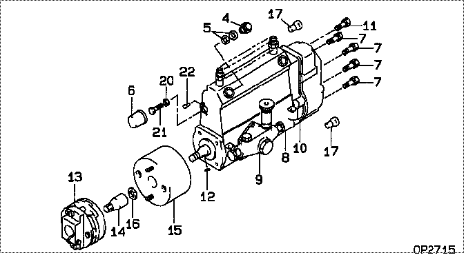
| 000. | [01] | 19100-05810 | PUMP ASSY, INJECTI | 22010-5490 |
| 004. | [01] | 09031-00130 | VALVE ASSY, OVERFL | 22107-1090A |
| 005. | [02] | 94901-02480 | WASHER | 22847-1940A |
| 006. | [01] | 09001-80401 | COVER, CONTROL RAC | 22114-1160A |
| 007. | [06] | 94904-71150 | BOLT, W/WASHER | 6 306 1001 00 |
| 008. | [01] | 09010-04642 | BODY ASSY, INJECTI | 22110-1731A |
| 009. | [01] | 09210-00920 | PUMP ASSY, FUEL FE | 22570-1250A |
| 010. | [01] | 19080-01590 | GOVERNOR ASSY, MEC | 22310-3790A |
| 011. | [01] | 94904-73910 | BOLT, W/WASHER | 22815-2820A |
| 012. | [01] | 94913-00210 | KEY, WOODRUFF | 22895-1010A |
| 013. | [01] | 09250-00270 | COUPLING ASSY | 22610-1080A |
| 014. | [01] | 09001-20180 | NUT, TIMER ROUND | 22511-1070A |
| 015. | [01] | 09180-01210 | TIMER ASSY, AUTOMA | 22510-1190A |
| 016. | [01] | 94901-50590 | WASHER, SPRING | 22877-1620A |
| 017. | [02] | 09028-50030 | CAP | 22323-1210A |
| 020. | [01] | 90170-06361 | NUT, HEXAGON | 92100-6040A |
| 021. | [01] | 09003-10070 | SCREW, CONTROL RAC | 22396-1210A |
| 022. | [02] | 09045-90030 | PIN | 22358-1010A |
Include in #3:
19100-05810
as PUMP ASSY, INJECTI
Cross reference number
| Part num | Firm num | Firm | Name |
| 19100-05810 | 22010-5490 | PUMP ASSY, INJECTI | |
| 22010-5490 | HINO | PUMP ASSY, INJECTI |
Information:
Dismantling
1. Dismantle the air filter with holder, disconnect the induction pipe from the air compressor and the fuel line from the torch heater. Unscrew the clip on the induction pipe securing the fuel pipe leading to the torch heater. Dismantle the exhaust manifold, induction manifold, air cowling, leak-off lines and fuel delivery lines.
3-1 Immediately the pipes are disconnected, plug the bores and fit caps over the connecting stubs of the fuel system.Fig. 3-12. Dismantle the cover plates for the cylinder head studs, back vertical plate, upper cover plate, exhaust air plate, rocker chamber covers and rocker arm shaft support. Remove the pushrods. Unscrew the plugs. (Use socket spanner No. 120040 and square-recess socket No. 120060).
3-2 On recent engines the square head of the plug is of modified design. The use of a regular tool is, however, possible.Fig. 3-23. To dismantle the cylinder head of the final cylinder, disassemble the screw securing it to the front vertical plate.
3-34. Slacken the cylinder head studs in stages, in diagonal sequence. (Use socket spanner No. 120040).Fig. 3-35. Remove the cylinder head and push-rod sheaths.Assembling
3-41. Align the cylinder.Fig. 3-4 Check/adjust piston crown clearance (see Section 2).
3-5 Where provided, install gasket.Fig. 3-52. Mount cylinder head after measuring length of head bolts.3. Renew those cylinder head studs that have stretched beyond the permissible maximum stated in the specifications.
3-64. Assemble and slightly tighten the studs fitted with washers. Align the induction and exhaust flanges of the cylinder heads without disturbing the alignment of the cylinders.Fig. 3-6
3-75. Tighten and lock down the studs in accordance with the instructions for tightening bolts and studs. (Use socket spanner No. 120040 and angle-of-turn indicator No. 101900).Fig. 3-7
3-86. Fit brass screwplugs with new gasket in the cylinder head.Fig. 3-8 Attention:The tightening torque for the brass screw-plugs is 80 + 10 Nm.
3-97. Assemble and tension the spring on the pushrod tube. (Use spring tensioning tool No. 125300).Fig. 3-9
3-108. Place on the profile washer with the domed side facing towards the spring. Fit a new sealing ring with the flat side facing towards the end of the pushrod tube.Fig. 3-10, left9. At the opposite end of the tube, fit a new sealing ring with the flat side facing towards the shoulder.Fig. 3-10, right
3-1110. Insert the spring ends of the two pushrod tubes in the pushrod holes in the crankcase and locate the upper ends with gaskets in the cones of the cylinder head. Remove the spring tensioner.Fig. 3-11Fitting Pushrod Cover Tubes On Engine Provided With Exhaust Air Heating
3-1211. Fit O-seals between the two grooves of the pushrod cover tubes as well as cover plate with gasket adhered thereto. Fitting order see Fig. 3-12.
3-1312. Put springs on pushrod cover tubes and tension springs. Spring tensioner No. 125300 (2x).Fig. 3-1313. Fit sectional washers and gaskets.
3-1414. Insert spring ends of both pushrod cover tubes with cover plates in the pushrod holes of the crankcase and locate the upper ends with gaskets in the cones of the cylinder head.Fig. 3-14
3-15 Insert cover plate between 2nd and 3rd