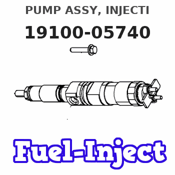
Information pump assy, injecti
Nozzle:
0935002080
Rating:
KIT List:
| Body assy, injecti | 1904400360 |
| Timer assy, automa | 0918030060 |
| Pump assy, fuel fe | 1922900060 |
| Governor assy, mec | 1908900190 |
Components :
| 001. | PUMP ASSY, INJECTI | 19100-05740 |
| 002. | BODY ASSY, INJECTI | 09010-04232 |
| 003. | COVER, BEARING | 09020-10410 |
| 004. | TIMER ASSY, AUTOMA | 09180-01210 |
| 005. | PUMP ASSY, FUEL FE | 09210-00920 |
| 006. | COUPLING ASSY | 09250-00270 |
| 007. | GOVERNOR ASSY, MEC | 19080-01570 |
| 008. | SWITCH KIT, CONTRO | 09009-90390 |
Scheme ###:
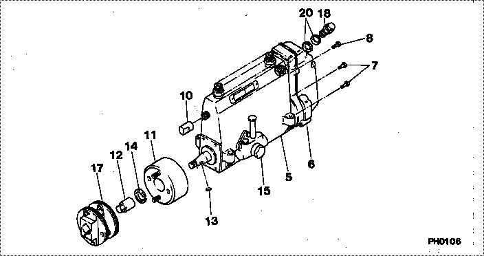
| 000. | [01] | 19100-05740 | PUMP ASSY, INJECTI | 22010-5400 |
| 005. | [01] | 09010-04232 | BODY ASSY, INJECTI | 22110-1590C |
| 006. | [01] | 19080-01570 | GOVERNOR ASSY, MEC | 22310-3690A |
| 007. | [06] | 94904-70620 | BOLT, W/WASHER | 22815-1620A |
| 008. | [01] | 94904-73910 | BOLT, W/WASHER | 22815-2820A |
| 010. | [01] | 09001-80081 | COVER, CONTROL RAC | 22114-1130A |
| 011. | [01] | 09180-01210 | TIMER ASSY, AUTOMA | 22510-1190A |
| 012. | [01] | 09001-20180 | NUT, TIMER ROUND | 22511-1070A |
| 013. | [01] | 94913-00210 | KEY, WOODRUFF | 22895-1010A |
| 014. | [01] | 94901-50590 | WASHER, SPRING | 22877-1620A |
| 015. | [01] | 09210-00920 | PUMP ASSY, FUEL FE | 22570-1250A |
| 017. | [01] | 09250-00270 | COUPLING ASSY | 22610-1080A |
| 018. | [01] | 09031-00130 | VALVE ASSY, OVERFL | 22107-1090A |
| 020. | [02] | 94901-02480 | WASHER | 22847-1940A |
Include in #3:
19100-05740
as PUMP ASSY, INJECTI
Cross reference number
| Part num | Firm num | Firm | Name |
| 19100-05740 | 22010-5400 | PUMP ASSY, INJECTI | |
| 22010-5400 | HINO | PUMP ASSY, INJECTI |
Information:
Dismantling:
8-4Remove V-belt and air cowling. Unscrew bolts and take down blower.Fig. 8-4Refitment:
8-51. Align blower to holes and attach to front-end cover.Fig. 8-5
8-62. Push idler pulley upward and install belt.Fig. 8-6Removing And Refitting Oil-Controlled Fan (As from 3-cylinder engine)
Removing Fan
Loosen generator and remove V-belt. Take down oil feed, vent and return piping. Unscrew bolts to remove fan.Refitting Fan
8-71. Align fan to holes and attach to front-end cover.Fig. 8-7
8-82. Fit oil return connector with new seal.Fig. 8-8
8-93. Connect oil return pipe with rubber sleeve and clips.Fig. 8-9 Fit new O-seal and coat with grease (arrow).Fig. 8-9
8-104. Connect vent pipe. Preload bolts.Fig. 8-10
8-115. Connect oil feed pipe. Preload bolts.Fig. 8-11
8-126. Secure clip as shown (arrow) and tighten all bolts.Fig. 8-12
8-137. Secure oil feed pipe to exhaust thermostat with new washers.Fig. 8-13Dismantling And Installing The Air Compressor And Bracket
Dismantling:
1. Remove the vee belts for the air compressor and generator. Disconnect the induction pipe attached to the air compressor and the oil line on the bracket.2. Remove the bracket with the air compressor. Disassemble the rubber O-seal on the bracket. Disassemble the air compressor from the bracket. Remove the rubber gasket from the contact surface of the air compressor.Installing:
8-141. Coat a new rubber gasket with grease and stick it in position on the air compressor.Fig. 8-14
8-152. Mount the air compressor on the bracket so that the oilholes of the compressor register with those of the bracket.Fig. 8-15
8-163. Apply grease to a new rubber gasket and stick it in position on the bracket.Fig. 8-16
8-174. Mount the bracket with air compressor to the front cover.Fig. 8-17
8-185. Fit new gasket on the oil line and connect it to the bracket.Fig. 8-18
8-196. Connect the induction line, fitted with a new gasket, to the air compressor, paying attention to the clamping cone.Fig. 8-19Tensioning, Replacing Air Compressor Vee-Belt
a) Single-Groove Pulley
1. Unscrew locking bolts from belt pulley, remove outer belt pulley and Vee-belt.
8-202. The belt tension is increased by removing shims from the collar of the inner belt pulley half.Fig. 8-203. Place removed shim on to outer belt pulley half.
8-214. Mount Vee-belt on collar. Fit outer belt pulley with inserted shims.Fig. 8-215. Fit bolts and tighten uniformly while turning the belt pulley.
8-226. Check Vee-belt tension. Make sure that the free movement midway between the belt pulleys is about 10 mm, when pressure is applied with the thumb.Fig. 8-227. If necessary, repeat the tensioning operation.b) Double-Groove Pulley
8-231. For tensioning the outer Vee-belt unscrew nuts and detach outer belt pulleyFig. 8-23
8-242. Remove one shim between outer belt pulley half and intermediate plate.Fig. 8-243. Place removed shim on the outside of the outer belt pulley half.4. Fit outer belt pulley half with shims and