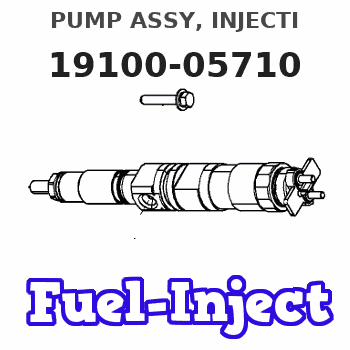
Information pump assy, injecti
Nozzle:
0935002540
Rating:
KIT List:
| Body assy, injecti | 1904400320 |
| Pump assy, fuel fe | 1922900060 |
| Governor assy, mec | 1908900170 |
Components :
| 001. | PUMP ASSY, INJECTI | 19100-05710 |
| 002. | BODY ASSY, INJECTI | 09010-08030 |
| 003. | PUMP ASSY, FUEL FE | 09210-01510 |
| 004. | GOVERNOR ASSY, MEC | 19080-01480 |
Scheme ###:
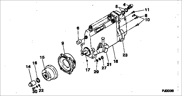
| 000. | [01] | 19100-05710 | PUMP ASSY, INJECTI | 22030-2290 |
| 000. | [01] | 19100-05710 | PUMP ASSY, INJECTI | S2203-02290 |
| 004. | [01] | 09031-00240 | VALVE ASSY, OVERFL | 22107-1290A |
| 005. | [02] | 94901-02480 | WASHER | 22847-1940A |
| 006. | [01] | 09001-80290 | COVER, CONTROL RAC | 22114-1020A |
| 008. | [01] | 91418-06141 | BOLT, W/WASHER | 22815-1480A |
| 008. | [01] | 91518-06121 | BOLT, W/WASHER | 22815-2740A |
| 009. | [01] | 09006-00150 | COVER SUB-ASSY, TI | 22825-1470A |
| 010. | [05] | 91418-06161 | BOLT, W/WASHER | 22815-1380A |
| 011. | [01] | 91518-08221 | BOLT, W/WASHER | 22815-1190A |
| 014. | [01] | 09001-20220 | NUT, TIMER ROUND | 22511-1060A |
| 015. | [01] | 09255-10420 | BLOCK, COUPLING | 22630-1030A |
| 016. | [01] | 94901-40210 | WASHER, COUNTERSUN | 22867-1320A |
| 017. | [01] | 90458-04051 | KEY, WOODRUFF | 22895-1080A |
| 018. | [01] | 09010-08030 | BODY ASSY, INJECTI | 22110-2620A |
| 021. | [01] | 09210-01510 | PUMP ASSY, FUEL FE | 22570-1240A |
| 022. | [04] | 09241-70060 | WASHER, COUPLING S | 22867-1490A |
| 023. | [01] | 19080-01480 | GOVERNOR ASSY, MEC | 22330-2250 |
| 027. | [04] | 91266-10081 | NUT, HEXAGON | 22825-1490A |
| 029. | [04] | 94901-15020 | WASHER, STEEL PLAT | 22877-1551A |
| 030. | [04] | 94904-04870 | BOLT, HEXAGON | 22815-2380A |
Include in #3:
19100-05710
as PUMP ASSY, INJECTI
19100-05710
Cross reference number
| Part num | Firm num | Firm | Name |
| 19100-05710 | 22030-2290 | PUMP ASSY, INJECTI | |
| 22030-2290 | HINO | PUMP ASSY, INJECTI | |
| S2203-02290 | HINO | PUMP ASSY, INJECTI |
Information:
1. Carefully clean crankcase, oil ducts in particulary check for free passage.2. Check walls and bearing webs for cracks.3. Check condition of bearing bores. If wear marks on bearing shells are not noticeable, check bearing bores with precision gauge. Attention:If there are signs of wear on the bearing shells, the line of bearing housings can be reworked to an oversize outside diameter on a line boring machine. It is not permissible to bore out individual bearing pedestals. Refer to Technical Circulars.Checking The Preload
4-14. Fit crankshaft bearing caps, observing the numbering, into the crankcase. Preload and tighten bolts according to instructions.(Fixture No. 101900)Fig. 4-1
4-25. Set precision gauge to the size indicated in the Technical Data, using a micrometer frame (nominal or oversize).Fig. 4-2
4-36. Measure each main bearing bore at the points 1 and 2 in plane "a", then in the same manner in plane "b" offset by 90 degrees, see also Fig. 4-6, in order to determine any contraction, out-of-roundness or conicity.Fig. 4-37. If the recorded values correspond to those specified in the Technical Data, the respective bearing bore is in acceptable condition and the required preload will be obtained when new bearing shells are installed.
4-48. If the recorded bearing bore diameters differ only slightly from the specified values, repeat the measurements with the new bearing shells installed.Fig. 4-49. Insert new bearing shells, mount bearing cap, then preload and tighten up according to instructions.
4-5
4-610. Gauge each bore at points 1 and 2 in the vertical and horizontal positions "a" and "b".Fig. 4-5 and 4-611. If the recordings show that the bearing tolerances are up to 0.020 mm max. above the values specified in the Technical Data, the crankcase is acceptable for further use. Otherwise, it is necessary for the line of bearing housings to be reworked to an oversize outside diameter on a line boring machine. It is not permissible to bore out individual bearing pedestals. Refer to Technical Circulars. Nor is it permissible to restore the required preload by underlaying the bearing shells or by reworking the parting faces of the bearing bores. a) The main bearing shells are made in two halves and supplied in six dimensions, corresponding to the specified undersizes of the journals. No attempt may be made to recondition the shells.
4-7b) Standard and oversize wall thickness "W" should be taken from the specifications.Fig. 4-7
4-812. Measure width of locating bearing journal of the crankshaft.Fig. 4-8
4-913. Assemble the thrust rings on the locating main bearing and calliper the overall width.Fig. 4-914. Measure end clearance. Compare with the values given in the specifications. If necessary, fit new stop rings.Replacing Bearing Bushing (F2L)
4-1015. Remove the radial seal ring from the back end shield.Fig. 4-10
4-1116. If the main bearing journal has not been re-ground and the bearing bushing shows no signs of damage or wear, gauge the bearing bore at two diagonal points.Fig. 4-1117. Compare measured values with the Specification Data. If necessary, fit new bearing bushing.
4-1218. Draw the bearing bushing in flush, with its oilholes in register with