Information pump assy, injecti
Nozzle:
0935003190
Rating:
KIT List:
| Body assy, injecti | 1904400300 |
| Governor assy, mec | 1908900250 |
| Pump assy, fuel fe | 1922900060 |
Components :
| 001. | PUMP ASSY, INJECTI | 19100-04790 |
| 002. | BODY ASSY, INJECTI | 09010-07760 |
| 003. | GOVERNOR ASSY, MEC | 09080-00951 |
| 003. | GOVERNOR ASSY, MEC | 09080-00951 |
| 004. | PUMP ASSY, FUEL FE | 09210-00701 |
Scheme ###:
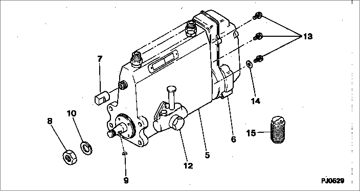
| 000. | [01] | 19100-04790 | PUMP ASSY, INJECTI | 30661-73010 |
| 005. | [01] | 09010-07760 | BODY ASSY, INJECTI | |
| 006. | [01] | 09080-00951 | GOVERNOR ASSY, MEC | 30661-39101 |
| 007. | [01] | 09001-80081 | COVER, CONTROL RAC | 09001-80081 |
| 008. | [01] | 94905-02450 | NUT, HEXAGON | 94905-02450 |
| 009. | [01] | 94913-00190 | KEY, WOODRUFF | 94913-00190 |
| 010. | [01] | 94901-50500 | WASHER, SPRING | 94901-50500 |
| 012. | [01] | 09210-00701 | PUMP ASSY, FUEL FE | 09210-00700 |
| 013. | [06] | 94904-70620 | BOLT, W/WASHER | |
| 014. | [01] | 90200-06511 | WASHER, PLATE | |
| 015. | [01] | 09006-10011 | COVER, PRIMING PUM | 09006-10011 |
Include in #3:
19100-04790
as PUMP ASSY, INJECTI
Cross reference number
| Part num | Firm num | Firm | Name |
| 19100-04790 | 30661-7301 | PUMP ASSY, INJECTI | |
| 30661-73010 | MITSUBISHI | PUMP ASSY, INJECTI |
Information:
Table 1
Item 3408C / 3412C 3176B 3176C / 3196
Connector P14 P1 P1
(-) Battery Pin-21 Pin-5 Pin-5
(+) 8 VDC Pin-10 Pin-35 Pin-35
Cat Data (+) Pin-9 Pin-9 Pin-9
Cat Data (-) Pin-19 Pin-3 Pin-3
Illustration 1 g06449052
(A) Port ECM
(B) Cat Link Booster
(C) EVIM
(D) STBD ECM
(E) CAT Link Booster
(F) Engine Vision Display
Illustration 2 g06449056
(G) Connector A
(H) Connector B
Turn the power OFF to the engine ECM and display unit.
Remove the ECM connector-battery pin and reinsert it into pin-3 on the 4-pin DT connector B (2).
Remove the ECM connector +8 VDC pin and reinsert into pin-4 on the 4-pin DT connector B (2).
Remove the ECM connector (CAT Data+) pin and reinsert into pin-1 on the 4-pin DT connector B (2).
Remove the ECM connector (Cat Data-) pin and reinsert into pin-2 on the 4-pin DT connector B (2).
Insert the BLACK wire into the ECM connector-battery pin.
Insert the PINK wire into the ECM connector CAT Data+ pin.
Insert the WHITE wire into the ECM connector CAT Data- pin.
Insert the RED wire into the ECM connector +8 VDC supply pin.
Plug connector B (2) into connector A (1).
Apply power to the ECM.