Information pump assy, injecti
Nozzle:
0935002070
Rating:
KIT List:
| Body assy, injecti | 1904400370 |
| Timer assy, automa | 0918030050 |
| Pump assy, fuel fe | 1922900060 |
| Governor assy, mec | 1908900180 |
Components :
| 001. | PUMP ASSY, INJECTI | 19100-04650 |
| 002. | BODY ASSY, INJECTI | 09010-07700 |
| 003. | TIMER ASSY, AUTOMA | 09180-00980 |
| 004. | PUMP ASSY, FUEL FE | 09210-02020 |
| 005. | GOVERNOR ASSY, MEC | 19080-01190 |
Scheme ###:
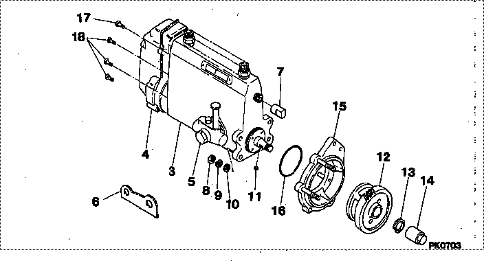
| 000. | [01] | 19100-04650 | PUMP ASSY, INJECTI | ME070019 |
| 003. | [01] | 09010-07700 | BODY ASSY, INJECTI | ME703930 |
| 004. | [01] | 19080-01190 | GOVERNOR ASSY, MEC | ME703926 |
| 005. | [01] | 09210-02020 | PUMP ASSY, FUEL FE | ME703799 |
| 006. | [01] | 09009-20100 | BRACKET | ME702036 |
| 007. | [01] | 09001-80081 | COVER, CONTROL RAC | ME702034 |
| 008. | [04] | 91266-10081 | NUT, HEXAGON | MF430122 |
| 010. | [04] | 94901-15020 | WASHER, STEEL PLAT | MH005068 |
| 011. | [01] | 94913-00210 | KEY, WOODRUFF | ME702047 |
| 012. | [01] | 09180-00980 | TIMER ASSY, AUTOMA | 31860-81040 |
| 013. | [01] | 94901-40210 | WASHER, COUNTERSUN | ME702043 |
| 014. | [01] | 09001-20220 | NUT, TIMER ROUND | ME702033 |
| 015. | [01] | 09006-00050 | COVER SUB-ASSY, TI | ME036902 |
| 016. | [01] | 94914-05680 | O-RING | ME728279 |
| 017. | [01] | 91518-08221 | BOLT, W/WASHER | MM500963 |
| 018. | [06] | 91418-06161 | BOLT, W/WASHER | ME702149 |
Include in #3:
19100-04650
as PUMP ASSY, INJECTI
Cross reference number
| Part num | Firm num | Firm | Name |
| 19100-04650 | ME070019 | PUMP ASSY, INJECTI | |
| ME070019 | MITSUBISHI | PUMP ASSY, INJECTI |
Information:
Table 1
Repair Kit Part Numbers for Quick Connect DEF Line Fittings
473-2053 5/16"-90 Degree Kit
473-2055 5/16"- Straight Kit
473-2056 3/8"-90 Degree Kit
473-2057 3/8"- Straight Kit Rework Procedure
Table 2
Required Tools
Part Number Part Name
1U-7648 Tube Cutter
Illustration 1 g06433660
Cut the connector end on the corrugated section with the cutter.
Illustration 2 g06433665
Cut the two wires with a tie cutter.
Illustration 3 g06433668
Use a knife or sharp blade to cut the outer sheathing off. Ensure not to cut or damage the inner fluid hose.
Illustration 4 g06433669
Install the hose clamp provided first before installing the connector. Use appropriate size (3/8th or 5/16th) and type (90 degree or straight) fitting.
Illustration 5 g06433672
Fasten the clamp until the two jaws are either in contact or about 2 to 3 mm (0.08 to 0.1 inch) apart.