Information pump assy, injecti
Nozzle:
0935000990
Rating:
KIT List:
| Body assy, injecti | No Application |
| Pump assy, fuel fe | 1922900060 |
| Governor assy, mec | 1908900170 |
Components :
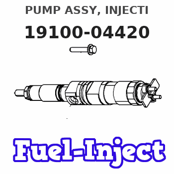
| 001. | PUMP ASSY, INJECTI | 19100-04420 |
| 002. | BODY ASSY, INJECTI | 09010-03220 |
| 003. | PUMP ASSY, FUEL FE | 09210-00073 |
| 004. | GOVERNOR ASSY, MEC | 19080-01060 |
Scheme ###:
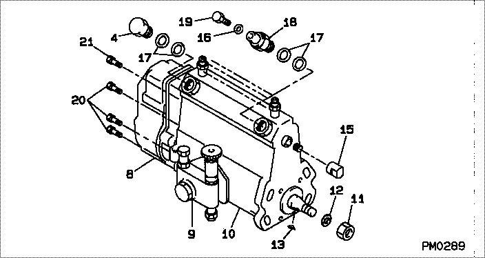
| 000. | [01] | 19100-04420 | PUMP ASSY, INJECTI | 01710860 |
| 004. | [01] | 94918-00310 | SCREW, HOLLOW | 21702980 |
| 008. | [01] | 19080-01060 | GOVERNOR ASSY, MEC | |
| 009. | [01] | 09210-00073 | PUMP ASSY, FUEL FE | 02001312 |
| 010. | [01] | 09010-03220 | BODY ASSY, INJECTI | 21706440 |
| 011. | [01] | 94905-02450 | NUT, HEXAGON | 21703380 |
| 012. | [01] | 94901-50500 | WASHER, SPRING | 21703370 |
| 013. | [01] | 94913-00190 | KEY, WOODRUFF | |
| 015. | [01] | 09001-80140 | COVER, CONTROL RAC | 21703400 |
| 016. | [01] | 94901-81020 | WASHER, COPPER PLA | 21706370 |
| 017. | [04] | 09022-20011 | WASHER, FUEL PIPE | 21703000 |
| 017. | [04] | 09022-20070 | WASHER, FUEL PIPE | |
| 018. | [01] | 09031-00011 | VALVE ASSY, OVERFL | 21701340 |
| 019. | [01] | 09024-40080 | SCREW, AIR BLEEDER | 21704700 |
| 020. | [06] | 91518-06161 | BOLT, W/WASHER | |
| 021. | [01] | 91518-08221 | BOLT, W/WASHER |
Include in #3:
19100-04420
as PUMP ASSY, INJECTI
Cross reference number
| Part num | Firm num | Firm | Name |
| 19100-04420 | 01710860 | PUMP ASSY, INJECTI | |
| 01710860 | MITSUI DEUTZ | PUMP ASSY, INJECTI |
Information:
Table 1
Item 3408C / 3412C 3176B 3176C / 3196
Connector P14 P1 P1
(-) Battery Pin-21 Pin-5 Pin-5
(+) 8 VDC Pin-10 Pin-35 Pin-35
Cat Data (+) Pin-9 Pin-9 Pin-9
Cat Data (-) Pin-19 Pin-3 Pin-3
Illustration 1 g06449052
(A) Port ECM
(B) Cat Link Booster
(C) EVIM
(D) STBD ECM
(E) CAT Link Booster
(F) Engine Vision Display
Illustration 2 g06449056
(G) Connector A
(H) Connector B
Turn the power OFF to the engine ECM and display unit.
Remove the ECM connector-battery pin and reinsert it into pin-3 on the 4-pin DT connector B (2).
Remove the ECM connector +8 VDC pin and reinsert into pin-4 on the 4-pin DT connector B (2).
Remove the ECM connector (CAT Data+) pin and reinsert into pin-1 on the 4-pin DT connector B (2).
Remove the ECM connector (Cat Data-) pin and reinsert into pin-2 on the 4-pin DT connector B (2).
Insert the BLACK wire into the ECM connector-battery pin.
Insert the PINK wire into the ECM connector CAT Data+ pin.
Insert the WHITE wire into the ECM connector CAT Data- pin.
Insert the RED wire into the ECM connector +8 VDC supply pin.
Plug connector B (2) into connector A (1).
Apply power to the ECM.