Information pump assy, injecti
Nozzle:
0935002680
Rating:
KIT List:
| Body assy, injecti | 1904400440 |
| Timer assy, automa | 0918030010 |
| Pump assy, fuel fe | 1922900060 |
| Governor assy, mec | 1908900210 |
Components :
| 001. | PUMP ASSY, INJECTI | 19100-02730 |
| 002. | BODY ASSY, INJECTI | 09010-06700 |
| 003. | COVER, BEARING | 09020-10110 |
| 004. | TIMER ASSY, AUTOMA | 09180-01761 |
| 004. | TIMER ASSY, AUTOMA | 09180-01761 |
| 005. | PUMP ASSY, FUEL FE | 09210-01940 |
| 006. | COUPLING ASSY | 09250-00631 |
| 007. | GOVERNOR ASSY, MEC | 19080-00370 |
Scheme ###:
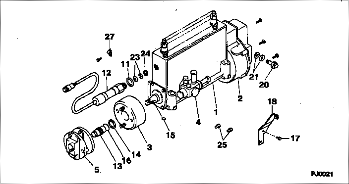
| 000. | [01] | 19100-02730 | PUMP ASSY, INJECTI | 22010-4610 |
| 001. | [01] | 09010-06700 | BODY ASSY, INJECTI | 22110-2160A |
| 002. | [01] | 19080-00370 | GOVERNOR ASSY, MEC | 22310-3140A |
| 003. | [01] | 09180-01761 | TIMER ASSY, AUTOMA | 22510-1630A |
| 004. | [01] | 09210-01940 | PUMP ASSY, FUEL FE | 22570-1350A |
| 005. | [01] | 09250-00631 | COUPLING ASSY | 22610-1470A |
| 011. | [01] | 94901-81820 | WASHER, COPPER PLA | 22847-2050A |
| 012. | [01] | 13650-00070 | SENSOR ASSY, POSIT | 21180-1480A |
| 013. | [01] | 09001-20230 | NUT, TIMER ROUND | 22825-1110A |
| 014. | [01] | 94901-40070 | WASHER, COUNTERSUN | 22877-1580A |
| 015. | [01] | 90458-05750 | KEY, WOODRUFF | 22891-1070A |
| 016. | [01] | 90801-40280 | O-RING | 22817-1050A |
| 017. | [02] | 94904-71970 | BOLT, W/WASHER | 22815-1510A |
| 018. | [01] | 09069-11170 | BRACKET, STOP WIRE | 22343-2770A |
| 020. | [01] | 09031-00130 | VALVE ASSY, OVERFL | 22107-1090A |
| 021. | [01] | 94901-02480 | WASHER | 22877-1090A |
| 023. | [ C] | 94901-37660 | WASHER, PLATE, SK | 22885-5670A |
| 023. | [ C] | 94901-37650 | WASHER, PLATE, SK | 22885-5660A |
| 023. | [ C] | 94901-37640 | WASHER, PLATE, SK | 22885-5650A |
| 023. | [ C] | 94901-37630 | WASHER, PLATE, SK | 22885-5640A |
| 024. | [01] | 94905-03540 | NUT, HEXAGON | 22825-2010A |
| 025. | [02] | 09028-50030 | CAP | 22323-1210A |
| 027. | [01] | 94935-01980 | CLIP, CORD | 22682-1010A |
Include in #3:
19100-02730
as PUMP ASSY, INJECTI
Cross reference number
| Part num | Firm num | Firm | Name |
| 19100-02730 | 22010-4610 | PUMP ASSY, INJECTI | |
| 22010-4610 | HINO | PUMP ASSY, INJECTI |
Information:
D5B (22X, 23X, 24X, 25X, 43X, 44X, 47X, 48X);
561D (54X)9G6065 Ether Starting Aid Group is an attachment that can be installed to help start direct injection engines in the above machines. See the instructions that follow for correct installation. Installation of the group is shown on a machine with bulldozer lines. Step 7 shows the changes necessary to install the group on a machine without bulldozer lines. (1) Remove the plug in the dash and install 3T306 Starting Aid Switch (1). Connect two purple wires (2), from the wiring harness, to switch (1).(2) On machines with a bulldozer, remove two nuts (3), washers and bolts. Remove two bolts (4) and washers. Remove bracket (5) from bracket (6). (3) Put 7G6359 Box Assembly (7) in position and install two 5F4899 Bolts (8) and 5M2894 Washers. Install two S1594 Bolts (9), 5P1075 Washers and 1D4717 Nuts to hold box assembly (7) to bracket (6). Install 4M7470 Grommet in hole (A).(4) Put the wires of 6N7674 Valve Assembly (10) through hole (A) and install valve assembly (10) on box assembly (7) with two S1617 Bolts (11), 5P4116 Washers and 1D4716 Nuts. Install 7N2059 Clamp Assembly (12) with two S1617 Bolts, 5P4116 Washers and 1D4716 Nuts. Install 63801 Washer (13) on 6D1746 Bolt (14). Put bolt (14) in position in cover (15) and install L1365 Washer (16) on bolt (14). Install 3B4610 Cotter Pin (17) in bolt (14). (5) Remove the plug from the manifold and install 6N9995 Atomizer Assembly (18) as shown. The orifices of the atomizer must be toward each end of the manifold. Install 5P7907 Connector (19) in valve assembly (10). Connect 9G941 Tube (20) to atomizer assembly (18). Use 5P6314 Sleeve (21) and 5P6313 Nut (22) to connect tube (20) to connector (19). Remove the plug from the bypass elbow of the water lines group and install 6N5899 Switch (23). Connect 9G6560 Wire Assembly (24) to switch (23) and to valve assembly (10). Connect 9G6561 Wire Assembly (25) to valve assembly (10) and to the purple wire, from the starting aid switch, at the rear of the engine. Use former clips (26) to hold wire assemblies (24) and (25) in position.(6) Remove cap (27) from valve assembly (10) and install a 7N296 Cylinder Assembly. (7) For machines without bulldozer lines, remove the two bolts from the cylinder head and put 7G6359 Box Assembly (7) in position. Install two 5F4899 Bolts (8) and 5M2894 Washers. Remove the bolt from the exhaust manifold and put 3T1685 Bracket (27) in position. Install L2070 Bolt (28), 5M2894 Washer and 1D4717 Nut. Install two S1594 Bolts (9), 5P1075 Washers and 1D4717 Nuts. Install the 4M7470 Grommet in hole (A), see Step 3. Follow Steps 1, 4, 5 and 6 for installation of the group.
561D (54X)9G6065 Ether Starting Aid Group is an attachment that can be installed to help start direct injection engines in the above machines. See the instructions that follow for correct installation. Installation of the group is shown on a machine with bulldozer lines. Step 7 shows the changes necessary to install the group on a machine without bulldozer lines. (1) Remove the plug in the dash and install 3T306 Starting Aid Switch (1). Connect two purple wires (2), from the wiring harness, to switch (1).(2) On machines with a bulldozer, remove two nuts (3), washers and bolts. Remove two bolts (4) and washers. Remove bracket (5) from bracket (6). (3) Put 7G6359 Box Assembly (7) in position and install two 5F4899 Bolts (8) and 5M2894 Washers. Install two S1594 Bolts (9), 5P1075 Washers and 1D4717 Nuts to hold box assembly (7) to bracket (6). Install 4M7470 Grommet in hole (A).(4) Put the wires of 6N7674 Valve Assembly (10) through hole (A) and install valve assembly (10) on box assembly (7) with two S1617 Bolts (11), 5P4116 Washers and 1D4716 Nuts. Install 7N2059 Clamp Assembly (12) with two S1617 Bolts, 5P4116 Washers and 1D4716 Nuts. Install 63801 Washer (13) on 6D1746 Bolt (14). Put bolt (14) in position in cover (15) and install L1365 Washer (16) on bolt (14). Install 3B4610 Cotter Pin (17) in bolt (14). (5) Remove the plug from the manifold and install 6N9995 Atomizer Assembly (18) as shown. The orifices of the atomizer must be toward each end of the manifold. Install 5P7907 Connector (19) in valve assembly (10). Connect 9G941 Tube (20) to atomizer assembly (18). Use 5P6314 Sleeve (21) and 5P6313 Nut (22) to connect tube (20) to connector (19). Remove the plug from the bypass elbow of the water lines group and install 6N5899 Switch (23). Connect 9G6560 Wire Assembly (24) to switch (23) and to valve assembly (10). Connect 9G6561 Wire Assembly (25) to valve assembly (10) and to the purple wire, from the starting aid switch, at the rear of the engine. Use former clips (26) to hold wire assemblies (24) and (25) in position.(6) Remove cap (27) from valve assembly (10) and install a 7N296 Cylinder Assembly. (7) For machines without bulldozer lines, remove the two bolts from the cylinder head and put 7G6359 Box Assembly (7) in position. Install two 5F4899 Bolts (8) and 5M2894 Washers. Remove the bolt from the exhaust manifold and put 3T1685 Bracket (27) in position. Install L2070 Bolt (28), 5M2894 Washer and 1D4717 Nut. Install two S1594 Bolts (9), 5P1075 Washers and 1D4717 Nuts. Install the 4M7470 Grommet in hole (A), see Step 3. Follow Steps 1, 4, 5 and 6 for installation of the group.