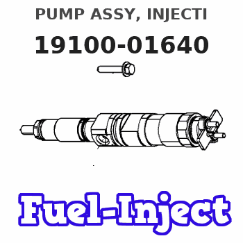
Information pump assy, injecti
Nozzle:
0935002080
Rating:
KIT List:
| Body assy, injecti | 1904400360 |
| Governor assy, mec | 1908900210 |
| Timer assy, automa | 0918030060 |
| Pump assy, fuel fe | 1922900060 |
Components :
| 001. | PUMP ASSY, INJECTI | 19100-01640 |
| 002. | SWITCH KIT, CONTRO | 09009-90390 |
| 003. | BODY ASSY, INJECTI | 09010-04232 |
| 004. | COVER, BEARING | 09020-10410 |
| 005. | TIMER ASSY, AUTOMA | 09180-01210 |
| 006. | PUMP ASSY, FUEL FE | 09210-00920 |
| 007. | COUPLING ASSY | 09250-00270 |
Scheme ###:
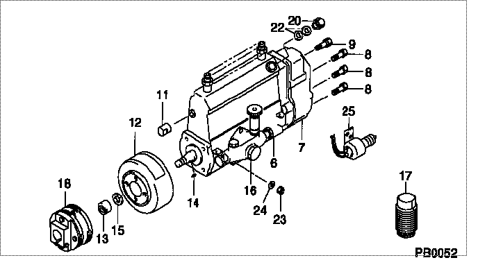
| 000. | [01] | 19100-01640 | PUMP ASSY, INJECTI | 22090-1400 |
| 006. | [01] | 09010-04232 | BODY ASSY, INJECTI | 22110-1590C |
| 007. | [01] | 09080-08910 | GOVERNOR ASSY, MEC | 22310-2710A |
| 008. | [06] | 94904-71150 | BOLT, W/WASHER | 6 306 1001 00 |
| 009. | [01] | 94904-73910 | BOLT, W/WASHER | 22815-2820A |
| 011. | [01] | 09001-80290 | COVER, CONTROL RAC | 22114-1020A |
| 012. | [01] | 09180-01210 | TIMER ASSY, AUTOMA | 22510-1190A |
| 013. | [01] | 09001-20180 | NUT, TIMER ROUND | 22511-1070A |
| 014. | [01] | 94913-00210 | KEY, WOODRUFF | 22895-1010A |
| 015. | [01] | 94901-50590 | WASHER, SPRING | 22877-1620A |
| 016. | [01] | 09210-00920 | PUMP ASSY, FUEL FE | 22570-1250A |
| 017. | [01] | 09006-10011 | COVER, PRIMING PUM | 6 053 1552 60 |
| 018. | [01] | 09250-00270 | COUPLING ASSY | 22610-1080A |
| 020. | [01] | 09031-00130 | VALVE ASSY, OVERFL | 22107-1090A |
| 022. | [02] | 94901-02480 | WASHER | 22847-1940A |
| 023. | [03] | 90160-06051 | NUT, HEXAGON | 22825-1480A |
| 024. | [03] | 90258-06001 | WASHER, SPRING | 28219-1110A |
| 025. | [01] | 09009-90390 | SWITCH KIT, CONTRO | 22690-1350A |
Include in #3:
19100-01640
as PUMP ASSY, INJECTI
Cross reference number
| Part num | Firm num | Firm | Name |
| 19100-01640 | 22090-1400 | PUMP ASSY, INJECTI | |
| 22090-1400 | HINO | PUMP ASSY, INJECTI |
Information:
Introduction
Do not perform any procedure in this Special Instruction until you have read the information and you understand the information.Required Tools
Table 1
Part Number Part Name Qty
- Flat-head screwdriver 1 Replacement Procedure
Illustration 1 g06099930
(1) Connector housing
(2) DCU
(3) Camlock connectors
Locate connector housings (1) on DCU (2). Disconnect the connectors from the DCU.
Illustration 2 g06099944
(1) Connector housing
(3) Camlock connector
(A) Flat-head screwdriver
Use a flat-head screwdriver (A) to pry the tab on the side of connector housing (1) up gently. Pull out on the camlock connector to disengage the locking tab.
Flip connector housing (1) over to the opposite side. Use a flat-head screwdriver (A) to pry the tab on the side of the connector housing up gently. Pull out on the camlock connector to disengage the locking tab.
Illustration 3 g06099938
(1) Connector housing
(3) Camlock connector
Remove camlock connector (3) from connector housing (1).
To install the new camlock connector (3), slide the camlock connector into connector housing (1). Once the camlock is pushed past the locking tabs, the camlock connector will be held in place.