Information pump assy, injecti
Nozzle:
0935002680
Rating:
KIT List:
| Body assy, injecti | No Application |
| Timer assy, automa | 0918030010 |
| Pump assy, fuel fe | 1922900070 |
| Governor assy, mec | 1908900190 |
Components :
| 001. | PUMP ASSY, INJECTI | 19100-01570 |
| 002. | BODY ASSY, INJECTI | 09010-06640 |
| 003. | COVER, BEARING | 09020-10110 |
| 004. | TIMER ASSY, AUTOMA | 09180-01771 |
| 004. | TIMER ASSY, AUTOMA | 09180-01771 |
| 005. | PUMP ASSY, FUEL FE | 09210-01900 |
| 006. | COUPLING ASSY | 09250-00631 |
| 007. | GOVERNOR ASSY, MEC | 19080-00130 |
Scheme ###:
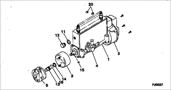
| 000. | [01] | 19100-01570 | PUMP ASSY, INJECTI | 22010-4460 |
| 001. | [01] | 09010-06640 | BODY ASSY, INJECTI | 22110-2140A |
| 002. | [01] | 19080-00130 | GOVERNOR ASSY, MEC | 22310-3090A |
| 003. | [01] | 09180-01771 | TIMER ASSY, AUTOMA | 22510-1610A |
| 004. | [01] | 09210-01900 | PUMP ASSY, FUEL FE | 22570-1330A |
| 005. | [01] | 09250-00631 | COUPLING ASSY | 22610-1470A |
| 011. | [01] | 94901-80710 | WASHER, COPPER PLA | 22863-1300A |
| 012. | [01] | 09001-80460 | COVER, CONTROL RAC | 22372-1140A |
| 013. | [01] | 09001-20230 | NUT, TIMER ROUND | 22825-1110A |
| 014. | [01] | 94901-40070 | WASHER, COUNTERSUN | 22877-1580A |
| 015. | [01] | 90458-05750 | KEY, WOODRUFF | 22891-1070A |
| 016. | [01] | 90801-40280 | O-RING | 22817-1050A |
| 020. | [02] | 09028-50030 | CAP | 22323-1210A |
Include in #3:
19100-01570
as PUMP ASSY, INJECTI
Cross reference number
| Part num | Firm num | Firm | Name |
| 19100-01570 | 22010-4460 | PUMP ASSY, INJECTI | |
| 22010-4460 | HINO | PUMP ASSY, INJECTI |
Information:
Introduction
This Special Instruction contains information for installing the Marine Fuel Flow Enclosure System on all Caterpillar and non-Caterpillar diesel engines. The Marine Fuel Flow Enclosure System will measure the amount of diesel fuel used by an engine. The system consists of two Fuel Flow Transducers and an Electronic Control Module (ECM) The ECM will measure/calculate the amount of fuel that is used, and will transmit this data, along with diagnostic information, on the main J1939 data link, Ethernet or Cat Data Link to be received by a recording ECM such as Product LinkSafety Section
Do not perform any procedure in this Special Instruction until you have read Special Instruction and you understand this information. Use only proper tools and observe all precautions that pertain to the use of those tools. Failure to follow these procedures can result in personal injury. The following procedures should also be observed.Work safely. Most accidents that involve product operation, maintenance, and repair are caused by failure to observe basic safety rules or precautions. An accident can often be avoided by recognizing potentially hazardous situations before an accident occurs. The installer must be alert to potential hazards and have the necessary training, skills, and tools needed to perform these functions properly. Wear safety equipment, such as eye protection, foot protection, and other protection as is appropriate to the work site.Safety precautions and warnings are provided in this instruction and on the product. If these hazard warnings are not heeded, bodily injury or death could occur to you or to other persons. Caterpillar cannot anticipate every possible circumstance that might involve a potential hazard. Therefore, the warnings in this publication and the warnings that are on the product are not all inclusive. Ensure that any tool, procedure, work method, or operating technique you use that is not recommended by Caterpillar is safe. Ensure that the product will not be damaged or the product will be made unsafe by the operation, lubrication, maintenance, or the repair procedures that are used.
Personal injury or death can result from improper assembly procedures.Do not attempt any assembly until you have read and understand the assembly instructions.
Accidental engine starting can cause injury or death to personnel working on the equipment.To avoid accidental engine starting, disconnect the battery cable from the negative (−) battery terminal. Completely tape all metal surfaces of the disconnected battery cable end in order to prevent contact with other metal surfaces which could activate the engine electrical system.Place a Do Not Operate tag at the Start/Stop switch location to inform personnel that the equipment is being worked on.
Prepare the Machine
If the machine is portable, then move the machine to a smooth, level surface that will support the weight of the machine.
Turn off the machine with the engine switch to the OFF position.
Use proper Lock out and Tag out procedures. Attach a "Do Not Operate" warning tag to the machine start switch or the controls before you perform any service to the machine. These warning tags Special Instruction, SEHS7332 are