Information pump assy, injecti
Rating:
Components :
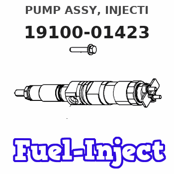
| 001. | PUMP ASSY, INJECTI | 19100-01423 |
| 001. | PUMP ASSY, INJECTI | 19100-01423 |
| 002. | SWITCH KIT, CONTRO | 09009-90450 |
| 003. | BODY ASSY, INJECTI | 09010-05700 |
| 004. | BODY ASSY, INJECTI | 09010-09960 |
| 005. | GOVERNOR ASSY, MEC | 09130-01190 |
| 006. | TIMER ASSY, AUTOMA | 09180-01281 |
| 006. | TIMER ASSY, AUTOMA | 09180-01281 |
| 007. | PUMP ASSY, FUEL FE | 09210-01440 |
Scheme ###:

| 000. | [01] | 19100-01422 | PUMP ASSY, INJECTI | ME035541 |
| 000. | [01] | 19100-01423 | PUMP ASSY, INJECTI | ME035541 |
| 005. | [01] | 09010-05701 | BODY ASSY, INJECTI | ME702012 |
| 005. | [01] | 09010-09960 | BODY ASSY, INJECTI | ME736047 |
| 006. | [01] | 09130-01193 | GOVERNOR ASSY, MEC | ME702256 |
| 007. | [01] | 09001-80081 | COVER, CONTROL RAC | ME702034 |
| 008. | [01] | 94914-02840 | O-RING | MH035502 |
| 009. | [01] | 09006-00050 | COVER SUB-ASSY, TI | ME036902 |
| 010. | [01] | 09180-01281 | TIMER ASSY, AUTOMA | ME036901 |
| 011. | [04] | 94905-02680 | NUT, HEXAGON | ME702046 |
| 012. | [04] | 90258-10001 | WASHER, SPRING | MC327716 |
| 013. | [04] | 94901-15020 | WASHER, STEEL PLAT | MH005068 |
| 015. | [01] | 94913-00210 | KEY, WOODRUFF | ME702047 |
| 016. | [01] | 94901-40210 | WASHER, COUNTERSUN | ME702043 |
| 017. | [01] | 09001-20220 | NUT, TIMER ROUND | ME702033 |
| 019. | [01] | 09210-01440 | PUMP ASSY, FUEL FE | ME035928 |
| 020. | [01] | 09009-20100 | BRACKET | ME702036 |
| 021. | [01] | 94904-73910 | BOLT, W/WASHER | ME703449 |
| 023. | [05] | 94904-72690 | BOLT, W/WASHER | ME702045 |
| 024. | [01] | 91418-06201 | BOLT, W/WASHER | ME702041 |
| 025. | [01] | 09009-90450 | SWITCH KIT, CONTRO | ME702011 |
| 026. | [01] | 09028-50021 | CAP | ME035845 |
| 027. | [01] | 09009-20140 | BRACKET | ME702037 |
| 028. | [01] | 91266-10081 | NUT, HEXAGON | MF430122 |
| 029. | [01] | 09028-50050 | CAP | ME076458 |
Include in #3:
19100-01423
as PUMP ASSY, INJECTI
Cross reference number
| Part num | Firm num | Firm | Name |
| 19100-01423 | ME035541 | PUMP ASSY, INJECTI |
Information:
Introduction
Note: Before starting the alignment procedure. Make a copy of the Generator Set Alignment Data Sheet that is located at the end of this Special Instruction.This Special Instruction is the recommended procedure for alignment of the two-bearing generators listed above.This procedure must be performed with all components at ambient temperature. Do not start the final alignment of the generator until the base is in the permanent position.Complete the initial and final alignment of the generator per this procedure. The generator must be resting on the resilient mounts for a minimum of 48 hours after ship is placed in the water, prior to checking alignment.Required Tools
Refer to Table 1 for the tools needed to perform the alignment check when using dial indicators.
Table 1
Required Tools
Qty Part Number
1 4C-5647 Pry Bar
2 8T-5096 Dial Indicator Gp
1 6V-2042 Yoke
1 6V-2043 Bar Procedure For Alignment
Note: The engine jacket water heaters must be switched off to allow the engine to reach the ambient room temperature. The generator space heaters must also be switched off. Run the prelube just prior to performing the alignment to provide an oil film on the bearings.To achieve correct operating alignment, the factors listed below have been considered in determining alignment specifications.
Illustration 1 g03003997
During the alignment procedure, the crankshaft lies at the bottom of each main bearing bore. Under running conditions, firing pressures, centrifugal forces, and engine oil pressure all tend to lift the crankshaft. Lifting of the crankshaft cause rotation around the center of the main bearing bores.
The weight of the flywheel and coupling cause a small deflection of the crankshaft during the alignment procedure.
During operation, the engine heat causes expansion of the metal in the engine and generator. The result of the expansion is a change in the locations of the centerlines of the crankshaft and generator shaft. The thermal expansion is greater in the crankshaft than the generator shaft. The centerline of the crankshaft will change more than the generator. Due to the change in the relationship of the centerline of the engine and the generator. The alignment procedure positions the centerline of the generator shaft above the centerline of the engine crankshaft.
In the past, a hot alignment check may have been used to check the accuracy of the cold alignment procedure. However, factory tests have shown that the results of the hot alignment check are inconsistent. Therefore, hot alignment is not recommended.Crankshaft End play
Measure the engine and generator end play. The end play readings should be within the specifications listed below:S/N: S/N:TAK
The split ring must be removed to take end play measurements. Reinstall the split ring prior to performing alignment.
Crankshaft end play is 0.178 mm (0.007 inch) to 0.640 mm (0.025 inch).
Generator end play is 0.348 mm (0.0137 inch) to 0.950 mm (0.0374 inch).S/N: S/N:NSC
This application does not utilize a split ring and there is sufficient clearance in the coupling to not interfere when taking end play measurements.
Crankshaft end play is 0.178 mm (0.007 inch) to 0.640 mm (0.025 inch).
Generator end play is 0.406