Information pump assy, injecti
Nozzle:
0935002890
Rating:
KIT List:
| Body assy, injecti | 1904400320 |
| Governor assy, mec | 1908900271 |
| Pump assy, fuel fe | 1922900060 |
Components :
| 001. | PUMP ASSY, INJECTI | 19100-01250 |
| 001. | PUMP ASSY, INJECTI | 19100-01250 |
| 002. | BODY ASSY, INJECTI | 09010-05690 |
| 002. | BODY ASSY, INJECTI | 09010-05690 |
| 003. | GOVERNOR ASSY, MEC | 09130-00780 |
| 003. | GOVERNOR ASSY, MEC | 09130-00780 |
| 004. | COVER ASSY, GOVERN | 09145-00232 |
| 004. | COVER ASSY, GOVERN | 09145-00232 |
| 005. | PUMP ASSY, FUEL FE | 09210-01850 |
| 005. | PUMP ASSY, FUEL FE | 09210-01850 |
Scheme ###:
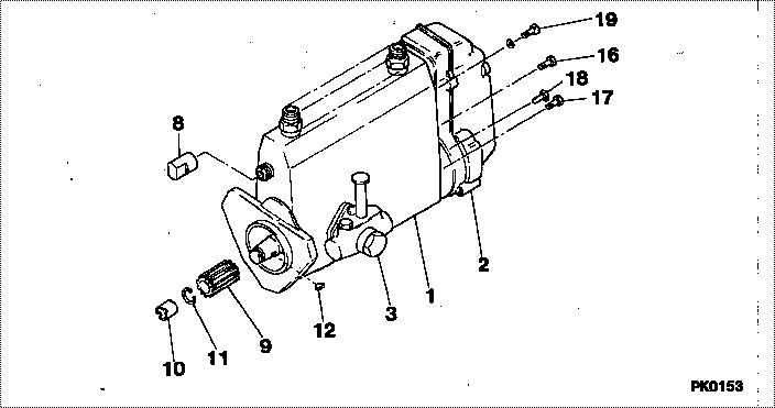
| 000. | [01] | 19100-01250 | PUMP ASSY, INJECTI | 22100-87C33-000 |
| 000. | [01] | 19100-01250 | PUMP ASSY, INJECTI | |
| 001. | [01] | 09010-05690 | BODY ASSY, INJECTI | |
| 001. | [01] | 09010-05690 | BODY ASSY, INJECTI | 22120-58230-000 |
| 002. | [01] | 09130-00780 | GOVERNOR ASSY, MEC | |
| 002. | [01] | 09130-00780 | GOVERNOR ASSY, MEC | 22410-58230-000 |
| 003. | [01] | 09210-01850 | PUMP ASSY, FUEL FE | |
| 003. | [01] | 09210-01850 | PUMP ASSY, FUEL FE | 22510-87307-000 |
| 008. | [01] | 09001-80090 | COVER, CONTROL RAC | 22114-1250A |
| 008. | [01] | 09001-80090 | COVER, CONTROL RAC | 22116-56230-000 |
| 009. | [01] | 09257-50170 | SHAFT, SPLINE | |
| 009. | [01] | 09257-50170 | SHAFT, SPLINE | 22174-58201-000 |
| 010. | [01] | 09001-20190 | NUT, TIMER ROUND | |
| 010. | [01] | 09001-20190 | NUT, TIMER ROUND | 22616-58200-000 |
| 011. | [01] | 94901-50590 | WASHER, SPRING | 22877-1620A |
| 011. | [01] | 94901-50590 | WASHER, SPRING | 90099-01449-000 |
| 012. | [01] | 94913-00210 | KEY, WOODRUFF | 90099-13023-000 |
| 012. | [01] | 94913-00210 | KEY, WOODRUFF | 22895-1010A |
| 016. | [01] | 91418-06201 | BOLT, W/WASHER | 90099-04564-000 |
| 016. | [01] | 91418-06201 | BOLT, W/WASHER | 22815-1290A |
| 017. | [04] | 94904-72690 | BOLT, W/WASHER | 90099-04319-000 |
| 017. | [04] | 94904-72690 | BOLT, W/WASHER | 22815-2410A |
| 018. | [01] | 94904-72990 | BOLT, W/WASHER | 90099-04320-000 |
| 018. | [01] | 94904-72990 | BOLT, W/WASHER | 22815-2420A |
| 019. | [01] | 94904-73910 | BOLT, W/WASHER | 90099-04346-000 |
| 019. | [01] | 94904-73910 | BOLT, W/WASHER | 22815-2820A |
Include in #3:
19100-01250
as PUMP ASSY, INJECTI
19100-01250
Cross reference number
| Part num | Firm num | Firm | Name |
| 19100-01250 | 22100-87C3 | PUMP ASSY, INJECTI | |
| 22100-87C33-000 | DAIHATSU | PUMP ASSY, INJECTI |
Information:
Introduction
Do not perform any procedure that is outlined in this Special Instruction until you read and understand the information that is contained in this document.Safety
Contact with high pressure fuel may cause personal injury or death. Wait 60 seconds after the engine has stopped to allow fuel pressure to purge before any service or repair is performed on the engine fuel lines.
Care must be taken to ensure that fluids are contained during performance of inspection, maintenance, testing, adjusting and repair of the product. Be prepared to collect the fluid with suitable containers before opening any compartment or disassembling any component containing fluids.Dispose of all fluids according to local regulations and mandates.
Keep all parts clean from contaminants.Contaminants may cause rapid wear and shortened component life.
Contact with high pressure fuel may cause fluid penetration and burn hazards. High pressure fuel spray may cause a fire hazard. Failure to follow these inspection, maintenance and service instructions may cause personal injury or death.
Required Tools
Table 1
Required Tools
Tool Part Number Part Name Qty
A
(1) 208-0888 Engine Turning Tool 1
B
(2) 5P-7305 Engine Turning Tool 1
5P-7306 Shaft Housing 1
C
(3) 350-7549 Engine Turning Tool 1
D 136-4632 Timing Pin 1
208-9388 Adapter 1
139-7064 Timing Pin Adapter 1
208-9387 Timing Pin Optional Longer Pin 1
E 294-3031 Fuel Pump Pinch Bolt 1
(1) The tooling is designed to turn the crankshaft in engines that are equipped with rear PTO. The tool engages the forward spline of upper gear of the PTO.
(2) The tooling is designed to turn the crankshaft in engines that are equipped with standard electric starters.
(3) The tooling is designed to turn the crankshaft in engines that have limited access to the flywheel housing. The tool engages all four bolt heads which are located in the front vibration damper.Removing the Fuel Injection Pump
Note: Cleanliness is a critical factor. Clean the exterior of the components before you begin the removal procedure. This action will help to prevent dirt from entering the internal mechanism.Note: Do not remove the valve mechanism cover at any time during this procedure.
Illustration 1 g02112896
Flywheel housing
Illustration 2 g06012763
Illustration 3 g02112894
Remove plug (X) from the timing hole that is located in the flywheel housing. Install the assembled timing pin (D) into the timing hole.
Use Tooling (A) or (B) to rotate the flywheel. Turn the flywheel in the direction of engine rotation. The direction of engine rotation is clockwise, as the engine is viewed from the vibration damper. Turn the vibration damper and the flywheel until the timing pin engages with the threaded hole in the flywheel.Note: If the flywheel is turned beyond the point of engagement, the flywheel must be turned in the direction that is reverse of normal engine rotation. Turn the flywheel by approximately 30 degrees. Then turn the flywheel in the direction of normal rotation until the timing pin engages with the threaded hole.
Remove all necessary components to access the fuel injection pump.