Information pump assy, injecti
Rating:
Components :
| 001. | PUMP ASSY, INJECTI | 19100-00961 |
| 002. | SWITCH KIT, CONTRO | 09009-90280 |
| 003. | BODY ASSY, INJECTI | 09010-06420 |
| 004. | COVER, BEARING | 09020-10110 |
| 005. | GOVERNOR ASSY, MEC | 09130-00721 |
| 006. | PUMP ASSY, FUEL FE | 09210-01900 |
| 007. | COUPLING ASSY | 09250-00401 |
Scheme ###:
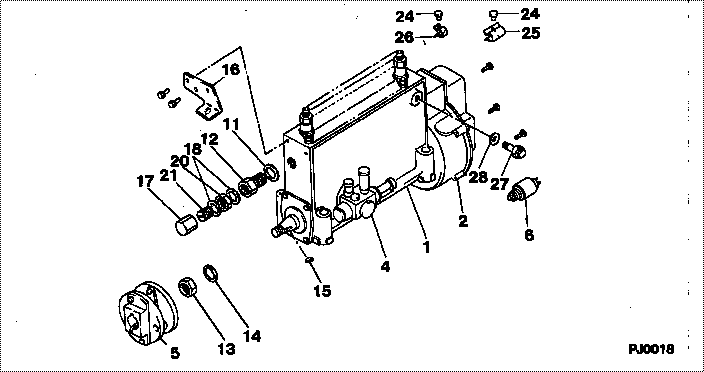
| 000. | [01] | 19100-00961 | PUMP ASSY, INJECTI | 22010-4221 |
| 001. | [01] | 09010-06420 | BODY ASSY, INJECTI | 22110-2120A |
| 002. | [01] | 09130-00721 | GOVERNOR ASSY, MEC | 22310-2632A |
| 002. | [01] | 09130-00722 | GOVERNOR ASSY, MEC | 22310-2632A |
| 004. | [01] | 09210-01900 | PUMP ASSY, FUEL FE | 22570-1330A |
| 005. | [01] | 09250-00401 | COUPLING ASSY | 22610-1330A |
| 006. | [01] | 09009-90280 | SWITCH KIT, CONTRO | 22690-1170A |
| 011. | [01] | 94901-80710 | WASHER, COPPER PLA | 22863-1300A |
| 012. | [01] | 09001-80152 | COVER, CONTROL RAC | 22372-1100A |
| 013. | [01] | 94905-03400 | NUT, HEXAGON | 22825-1730A |
| 014. | [01] | 94901-50730 | WASHER, SPRING | 22877-1670A |
| 015. | [01] | 90458-05750 | KEY, WOODRUFF | 22891-1070A |
| 016. | [01] | 09008-80040 | BRACKET ASSY | 22451-1150A |
| 017. | [01] | 09003-20040 | CAP | 22342-1110A |
| 018. | [02] | 94901-80350 | WASHER, COPPER PLA | 22847-1950A |
| 020. | [01] | 94805-30100 | NUT, HEXAGON, W/HO | 22885-3830A |
| 021. | [01] | 09002-60050 | SCREW, ADJUSTING | 22396-1140A |
| 024. | [02] | 09001-60060 | SEAL, LEAD | 22323-1200A |
| 025. | [01] | 09039-10050 | CLIP, CORD | 22323-1250A |
| 026. | [01] | 09039-10060 | CLIP, CORD | 22323-1240A |
| 027. | [01] | 09031-00260 | VALVE ASSY, OVERFL | 22107-1380A |
| 028. | [03] | 94901-02490 | WASHER | 22877-1100A |
Include in #3:
19100-00961
as PUMP ASSY, INJECTI
Cross reference number
| Part num | Firm num | Firm | Name |
| 19100-00961 | 22010-4221 | PUMP ASSY, INJECTI |
Information:
Introduction
Do not perform any procedure in this Special Instruction until you have read this information and you understand this information.Required Parts
Table 1
Required Parts
Item Qty New Part Number Part Name
1 2 137-8101 O-Ring Seal
2 2 286-5030 Elbow
3 1 289-3891 Clip
4 1 294-6118 Pressure Sensor
5 1 356-0920 Bracket
6 2 3J-7352 Connector
7 2 6V-5048 O-Ring Seal
8 2 8T-0267 Bolt
9 2 9X-8267 Washer
10 108-9656 Cable Straps
11 2 5P-1717 Hose Clamp
12 1 356-6802 Sensor Harness As
13 1 289-3891 Clip
14 2 5P-3860 Hose Clamp Procedure
Illustration 1 g02082554
Example of a vertical filter group (1) Connection for the pressure sensor group (2) New bypass wiring harness (3) Connection for the mounted sensor group (4) OEM wiring harness connection (5) OEM wiring harness (6) Wire for the probe of the outlet temperature is secured to the new P1 tube. (7) Support bracket for the new P1 tube (8) New P1 tube (9) The wire for the probe for the inlet temperature is secured to new P1 tube. (10) New P2 tubeNote: Avoid placing