Information pump assy, injecti
Nozzle:
0935002890
Rating:
KIT List:
| Body assy, injecti | 1904400320 |
| Governor assy, mec | 1908900271 |
| Pump assy, fuel fe | 1922900060 |
Components :
| 001. | PUMP ASSY, INJECTI | 19100-00710 |
| 002. | BODY ASSY, INJECTI | 09010-05760 |
| 003. | GOVERNOR ASSY, MEC | 09130-01110 |
| 004. | COVER ASSY, GOVERN | 09145-00313 |
| 005. | PUMP ASSY, FUEL FE | 09210-01700 |
Scheme ###:
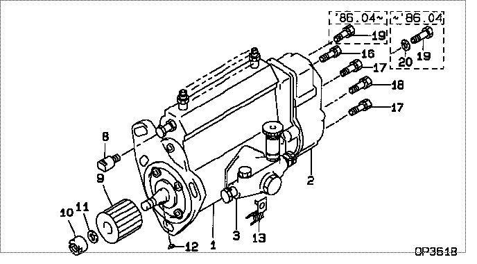
| 000. | [01] | 19100-00710 | PUMP ASSY, INJECTI | 22100-58280 |
| 001. | [01] | 09010-05760 | BODY ASSY, INJECTI | 22120-58290 |
| 002. | [01] | 09130-01110 | GOVERNOR ASSY, MEC | 22410-58250 |
| 003. | [01] | 09210-01700 | PUMP ASSY, FUEL FE | 22510-873 |
| 008. | [01] | 09001-80090 | COVER, CONTROL RAC | 22116-56230 |
| 009. | [01] | 09257-50170 | SHAFT, SPLINE | 22174-58201 |
| 010. | [01] | 09001-20190 | NUT, TIMER ROUND | 22611-58200 |
| 011. | [01] | 94901-50590 | WASHER, SPRING | 90099-01449 |
| 012. | [01] | 94913-00210 | KEY, WOODRUFF | 90099-13023 |
| 013. | [01] | 09048-10030 | CLAMP, HOSE | 90929-01132 |
| 016. | [01] | 91418-06201 | BOLT, W/WASHER | 90091-20608 |
| 017. | [04] | 94904-72690 | BOLT, W/WASHER | 90099-04319 |
| 018. | [01] | 94904-72990 | BOLT, W/WASHER | 90099-04320 |
| 018. | [01] | 94904-74850 | BOLT, W/WASHER | 90099-04415 |
| 019. | [01] | 94904-04300 | BOLT, HEXAGON | 90031-01132 |
| 019. | [01] | 94904-73910 | BOLT, W/WASHER | 90099-04346 |
| 020. | [01] | 90258-08001 | WASHER, SPRING | 94511-00800 |
Include in #3:
19100-00710
as PUMP ASSY, INJECTI
Cross reference number
| Part num | Firm num | Firm | Name |
| 19100-00710 | 22100-5828 | PUMP ASSY, INJECTI | |
| 22100-58280 | TOYOTA | PUMP ASSY, INJECTI |
Information:
Illustration 1 g01046024
Engine with two turbochargers (1) Inlet valves (2) Exhaust valves (3) Inlet manifold (4) Exhaust manifold (5) Water inlet for the aftercooler (6) Water outlet for the aftercooler (7) Aftercooler (8) Air inlet (9) Exhaust outlet (10) Compressor (11) TurbineThe components of the air inlet and exhaust system control the quality of air and the amount of air that is available for combustion. The components of the air inlet and exhaust system are the following components:
Air cleaner
Turbocharger
Aftercooler
Cylinder head
Valves and valve system components
Piston and cylinder
Inlet manifold
Exhaust manifoldNote: The following description of the operation of the air inlet and exhaust system assumes that the engine is developing boost pressure. Inlet air passes through the air cleaner into the air inlet (8) of the turbocharger compressor wheel (10). The turbocharger will supply more volume of air into the engine. This compressing of the air is referred to as boost. The compressing of air causes the air temperature to rise to about 204 °C (400 °F). As the air flows through the aftercooler (7) the temperature of the compressed air lowers to about 46 °C (115 °F). Cooling of the inlet air causes the air to become more dense. This increases combustion efficiency and this increases horsepower output.From the aftercooler, air enters the inlet manifold (3). Air flow from the inlet manifold (3) into the cylinders is controlled by inlet valves (1). There are two inlet valves and two exhaust valves (2) for each cylinder. The inlet valves open at the top center position before the piston moves toward the bottom center position. This is called the inlet stroke. When the inlet valves open, cooled compressed air from the inlet port enters the cylinder. The inlet valves close as the piston reaches the bottom center position. The piston begins to travel back to the top center position on the compression stroke. The air in the cylinder is compressed to a very high temperature. When the piston is near the end of the compression stroke, fuel is injected into the cylinder and mixes with the air. This causes combustion to start in the cylinder. Once combustion starts, the combustion force pushes the piston toward the bottom center position. This is called the power stroke. The exhaust valves open when the piston moves toward the bottom center position and the exhaust gases are pushed through the exhaust port into exhaust manifold (4) as the piston travels toward top center on the exhaust stroke. The exhaust valves close and the cycle starts again. The complete cycle consists of four strokes:
Inlet
Compression
Power
ExhaustExhaust gases from the exhaust manifold (4) enter the turbine side of the turbocharger. The exhaust gas temperature causes the turbine wheel (11) in the turbocharger to turn. The turbine wheel is connected to the shaft that drives the compressor wheel. Exhaust gases from the turbine wheel exit the turbocharger (9) .Turbocharger
Illustration 2 g01361124
Water cooled turbocharger (8) Air inlet (9) Exhaust outlet (11) Exhaust inlet (12) Compressor housing (13) Compressor wheel (14) Bearing (15) Oil Inlet