Information pump assy, injecti
Rating:
Components :
| 001. | PUMP ASSY, INJECTI | 19100-00263 |
| 001. | PUMP ASSY, INJECTI | 19100-00263 |
| 001. | PUMP ASSY, INJECTI | 19100-00263 |
| 001. | PUMP ASSY, INJECTI | 19100-00263 |
| 002. | BODY ASSY, INJECTI | 09010-06090 |
| 003. | COVER, BEARING | 09020-10430 |
| 004. | BODY ASSY, INJECTI | 09010-06710 |
| 005. | GOVERNOR ASSY, MEC | 09080-09420 |
| 005. | GOVERNOR ASSY, MEC | 09080-09420 |
| 006. | PUMP ASSY, FUEL FE | 09210-01761 |
| 007. | COUPLING ASSY | 09250-00440 |
Scheme ###:
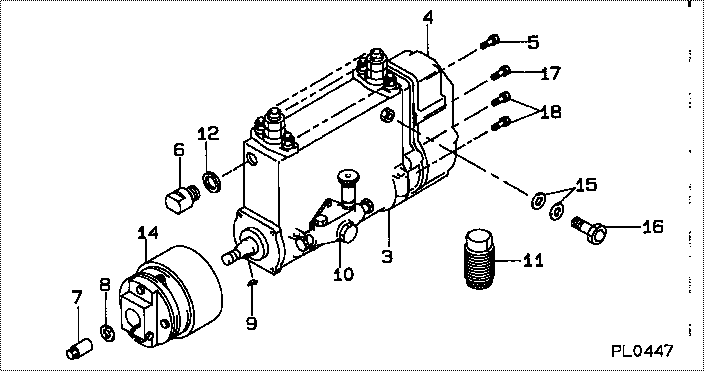
| 000. | [01] | 19100-00260 | PUMP ASSY, INJECTI | 61507-12532 |
| 000. | [01] | 19100-00261 | PUMP ASSY, INJECTI | 61507-12532 |
| 000. | [01] | 19100-00262 | PUMP ASSY, INJECTI | 61507-12532 |
| 000. | [01] | 19100-00263 | PUMP ASSY, INJECTI | 61507-12532 |
| 003. | [01] | 09010-06091 | BODY ASSY, INJECTI | |
| 003. | [01] | 09010-06710 | BODY ASSY, INJECTI | |
| 003. | [01] | 09010-06090 | BODY ASSY, INJECTI | |
| 004. | [01] | 09080-09420 | GOVERNOR ASSY, MEC | |
| 004. | [01] | 09080-09421 | GOVERNOR ASSY, MEC | |
| 005. | [02] | 94904-70620 | BOLT, W/WASHER | 94904-70620 |
| 006. | [01] | 09001-80410 | COVER, CONTROL RAC | |
| 007. | [01] | 09001-20140 | NUT, TIMER ROUND | |
| 008. | [01] | 94901-40070 | WASHER, COUNTERSUN | |
| 009. | [01] | 90458-05750 | KEY, WOODRUFF | |
| 010. | [01] | 09210-01761 | PUMP ASSY, FUEL FE | |
| 011. | [01] | 09006-10011 | COVER, PRIMING PUM | 09006-10011 |
| 012. | [01] | 94901-81550 | WASHER, COPPER PLA | |
| 014. | [01] | 09250-00441 | COUPLING ASSY | |
| 014. | [01] | 09250-00440 | COUPLING ASSY | |
| 015. | [02] | 09022-20070 | WASHER, FUEL PIPE | 09022-20070 |
| 016. | [01] | 09031-00080 | VALVE ASSY, OVERFL | |
| 017. | [02] | 91418-06201 | BOLT, W/WASHER | 91418-06201 |
| 018. | [04] | 91518-06161 | BOLT, W/WASHER | 91518-06161 |
Include in #3:
19100-00263
as PUMP ASSY, INJECTI
Cross reference number
| Part num | Firm num | Firm | Name |
| 19100-00263 | 61507-1253 | PUMP ASSY, INJECTI |
Information:
Introduction
Do not perform any procedure in this Special Instruction until you have read this information and you understand this information.Remove the Fuse for the ARD Purge Air Pump
Note: The fuse must be removed before performing this procedure. If the fuse has not been removed, the fuse can be blown when the jumper harness is installed.
Remove the fuse for the ARD purge air pump. Consult the manufacturer of the chassis for the location of the fuse.Installing the Software
Note: The software must be updated before the iron is updated.
Update Cat ET to the ET2008A or a later version.
Download the current data for the truck.
The new software must be flashed before the engine is updated with the hardware. Damage will occur if the hardware is updated first.
Flash new software into the engine ECM. The software must be updated to 320-XXXX or later.
Illustration 1 g01443782
Set the configuration in Cat ET. Refer to Illustration 1.
Select "Emissions Parameters".
Select "ARD Fuel Nozzle Cleaner Configuration A".
Select "Nozzle Heater".Jumper Harness
Use the following procedure in order to complete the jumper harness.
Disconnect the electrical connector for the ARD purge air pump from the engine harness.
Check the engine harness connector for the ARD purge air pump. There are two possible configurations for the engine wiring:
If four wires are inserted into the engine harness connector for the ARD purge air pump, the engine wiring is already configured for the heated nozzle. Proceed to the ""Installing the Hardware"" section of this procedure. Note: This is effective with (S/N: SDP8270-UP) and (S/N: LEE6575-UP).
If three wires are inserted into the engine harness connector for the ARD purge air pump, the engine wiring is not configured for the heated nozzle. Continue with this procedure in order to configure the engine wiring for the heated nozzle.
Cut the three wires that are inserted into the engine harness connector for the ARD purge air pump. Be sure to cut the wires near the engine harness connector. Discard the electrical connector.
Crimp a new terminal onto the end of each wire.
Illustration 2 g01454961
Refer to Illustration 2 before you insert the wires into the 230-5008 Connector Plug As . Insert the pink wire into location 1. Insert the red wire into location 3. Insert the black wire into location 4. Insert the orange wire from the 317-0642 Wiring Kit into terminal 2.Note: The pink wire, the red wire, and the black wire are the wires from the engine harness. The orange wire is from the 317-0642 Wiring Kit .
Pull on each wire in order to verify that wire is fully inserted into the electrical connector.
Illustration 3 g01469937
Electrical schematic for the ARD purge air system
Illustration 4 g01469897
Electrical schematic for the heated nozzleInstalling the Hardware
Illustration 5 g01443304
(1) ARD purge air pump
Remove pump (1) and remove the associated components. Remove the lines for the purge air as well as the tee for the purge air. Install 9S-5518 Plug . Discard the pump and the components. Remove the cleaning port and the lines for the cleaning port.Note: Maintain cleanliness in order to prevent contamination.
There are two options for